Nissan Juke F15. Manual - part 615


  Index      Nissan     Nissan Juke F15 (2015 year) - Service and Repair Manual


Search            


Content   ..  613  614  615  616   ..


Nissan Juke F15. Manual - part 615


EM-14

< BASIC INSPECTION >

[MR FOR NISMO RS MODELS]

CAMSHAFT VALVE CLEARANCE

BASIC INSPECTION

CAMSHAFT VALVE CLEARANCE

Inspection and Adjustment

INFOID:0000000012197237

INSPECTION

Perform inspection as follows after removal, installation or replacement of camshaft or valve-related parts, or if

there is unusual engine conditions regarding valve clearance. 
1. Remove rocker cover. Refer to 

EM-60, "Exploded View"

.

2. Measure the valve clearance with the following procedure:
a. Set No. 1 cylinder at TDC of its compression stroke.

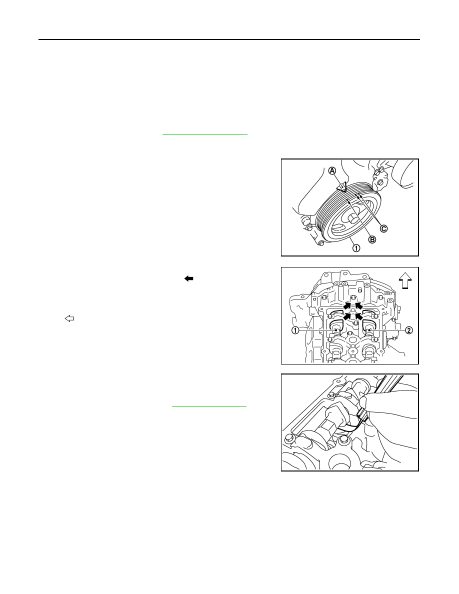
• Rotate crankshaft pulley (1) clockwise and align TDC mark (no

paint) (B) to timing indicator (A) on front cover.

• At the same time, check that both intake and exhaust cam

noses of No. 1 cylinder face inside (

) as shown in the figure.

• If they do not face inside, rotate crankshaft pulley once more

(360 degrees) and align as shown in the figure.

b. Use a feeler gauge, measure the clearance between valve lifter

and camshaft. 

C : White paint mark (Not use for service)

PBIC3960E

1

: Camshaft (INT)

2

: Camshaft (EXH)

: Engine front

JPBIA4347ZZ

Valve clearance

: Refer to 

EM-140, "Camshaft"

.

PBIC3192J

CAMSHAFT VALVE CLEARANCE

EM-15

< BASIC INSPECTION >

[MR FOR NISMO RS MODELS]

C

D

E

F

G

H

I

J

K

L

M

A

EM

N

P

O

• By referring to the figure, measure the valve clearances at

locations marked “

×” as shown in the table below [locations

indicated with black arrow (

) in the figure] with a feeler

gauge.

c. Set No. 4 cylinder at TDC of its compression stroke.

• Rotate crankshaft pulley (1) one revolution (360 degrees) and

align TDC mark (no paint) (B) to timing indicator (A) on front

cover. 

• By referring to the figure, measure the valve clearance at loca-

tions marked “

×” as shown in the table below [locations indi-

cated with black arrow (

) in the figure] with a feeler gauge. 

3. If out of standard, perform adjustment. Refer to “ADJUSTMENT”.

ADJUSTMENT

• Perform adjustment depending on selected head thickness of valve lifter.
1. Remove camshaft. Refer to 

EM-88, "Exploded View"

.

2. Remove valve lifters at the locations that are out of the standard.

A

: Exhaust side

B

: No. 1 cylinder

C

: No. 2 cylinder

D

: No. 3 cylinder

E

: No. 4 cylinder

F

: Intake side

: Engine front

JPBIA4348ZZ

Measuring position

No. 1 CYL.

No. 2 CYL.

No. 3 CYL.

No. 4 CYL.

No. 1 cylinder at compression TDC

EXH

×

×

INT

×

×

C : White paint mark (Not use for service)

PBIC3960E

A

: Exhaust side

B

: No. 1 cylinder

C

: No. 2 cylinder

D

: No. 3 cylinder

E

: No. 4 cylinder

F

: Intake side

: Engine front

JPBIA4349ZZ

Measuring position

No. 1 CYL.

No. 2 CYL.

No. 3 CYL.

No. 4 CYL.

No. 4 cylinder at compression TDC

EXH

×

×

INT

×

×

EM-16

< BASIC INSPECTION >

[MR FOR NISMO RS MODELS]

CAMSHAFT VALVE CLEARANCE

3. Measure the center thickness of the removed valve lifters with a

micrometer (A).

4. Use the equation below to calculate valve lifter thickness for replacement.

• Thickness of new valve lifter (B) can be identified by stamp

mark (A) on the reverse side (inside the cylinder).

• Stamp mark “302” indicates 3.02 mm (0.1189 in) in thickness.

NOTE:

Available thickness of valve lifter: 26 sizes range 3.00 to 3.50 mm (0.1181 to 0.1378 in) in steps of 0.02

mm (0.0008 in) (when manufactured at factory). Refer to 

EM-140, "Camshaft"

.

5. Install the selected valve lifter.
6. Install camshaft. Refer to 

EM-88, "Exploded View"

.

7. Install timing chain and related parts. Refer to 

EM-76, "Exploded View"

.

8. Manually rotate crankshaft pulley a few rotations. 
9. Check that the valve clearances is within the standard. Refer to “INSPECTION”.
10. Install remaining parts in the reverse order of removal.
11. Warm up the engine, and check for unusual noise and vibration.

PBIC3195J

Valve lifter thickness calculation:

t = t

1

 + (C

– C

2

)

t

= Valve lifter thickness to be replaced

t

1

= Removed valve lifter thickness

C

1

= Measured valve clearance

C

2

= Standard valve clearance:

Intake

: 0.28 mm (0.011 in)

Exhaust

: 0.29 mm (0.011 in)

PBIC3196J

COMPRESSION PRESSURE

EM-17

< BASIC INSPECTION >

[MR FOR NISMO RS MODELS]

C

D

E

F

G

H

I

J

K

L

M

A

EM

N

P

O

COMPRESSION PRESSURE

Inspection

INFOID:0000000012197238

1. Warm up engine thoroughly. Then, stop it.
2. Release fuel pressure. Refer to 

EC-166, "Work Procedure"

.

3. Remove ignition coil and spark plug from each cylinder. Refer to 

EM-60, "Exploded View"

.

4. Connect engine tachometer (not required in use of CONSULT).
5. Install compression gauge (B) with an adapter (A) (commercial

service tool) onto spark plug hole.

• Use the adapter whose picking up end inserted to spark plug

hole is smaller than 20 mm (0.79 in) in diameter. Otherwise, it

may be caught by cylinder head during removal.

6. With accelerator pedal fully depressed, turn ignition switch to “START” for cranking. When the gauge

pointer stabilizes, read the compression pressure and the engine rpm. Perform these steps to check each

cylinder.

CAUTION:

Always use a fully charged battery to obtain the specified engine speed.

• If the engine speed is out of the specified range, check battery liquid for proper gravity. Check the

engine speed again with normal battery gravity. 

• If compression pressure is below minimum value, check valve clearances, and parts associated with

combustion chamber (valve, valve seat, piston, piston ring, cylinder bore, cylinder head, and cylinder

head gasket). After the checking, measure compression pressure again.

• If some cylinder has low compression pressure, pour small amount of engine oil into the spark plug hole

of the cylinder to recheck it for compression.

- If the added engine oil improves the compression, piston rings may be worn out or damaged. Check pis-

ton rings and replace if necessary.

- If the compression pressure remains at low level despite the addition of engine oil, valves may be mal-

functioning. Check valves for damage. Replace valve or valve seat accordingly.

• If two adjacent cylinders have respectively low compression pressure and their compression remains

low even after the addition of engine oil, cylinder head gaskets are leaking. In such a case, replace cyl-

inder head gaskets.

7. After inspection is completed, install removed parts.
8. Start the engine, and check that the engine runs smoothly.
9. Perform trouble diagnosis. If DTC appears, erase it. Refer to 

EC-180, "Description"

.

PBIC3541J

a

: 20 mm (0.79 in)

JPBIA0171ZZ

Compression pressure : Refer to 

EM-139, "General Specification"

.


Content   ..  613  614  615  616   ..