Nissan Juke F15. Manual - part 284


  Index      Nissan     Nissan Juke F15 (2015 year) - Service and Repair Manual


Search            


Content   ..  282  283  284  285   ..


Nissan Juke F15. Manual - part 284


FRONT OIL SEAL

DLN-141

< REMOVAL AND INSTALLATION >

[REAR FINAL DRIVE: RTVS]

C

E

F

G

H

I

J

K

L

M

A

B

DLN

N

O

P

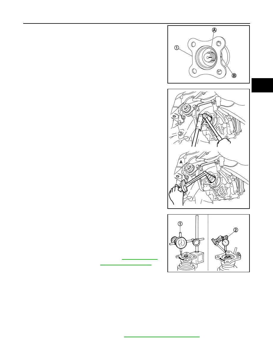
3. Align the matching mark (A) of drive pinion with the matching

mark (B) of companion flange (1), and then install the compan-

ion flange.

4. Temporarily tighten drive pinion lock nut to drive pinion, using

the flange wrench (Commercial service tool).

CAUTION:

• Never reuse drive pinion lock nut.

• Apply anti-corrosion oil to the thread and seat of new

drive pinion lock nut.

5. Tighten drive pinion lock nut within the limits of specified torque

so as to keep the pinion bearing preload within a standard val-

ues, using the preload gauge (A) [SST: ST3127S000 (J-25765-

A)].

CAUTION:

• Adjust to the lower limit of the drive pinion lock nut tight-

ening torque first.

• If the preload torque exceeds the specified value, replace

collapsible spacer and tighten it again to adjust. Never

loosen drive pinion lock nut to adjust the preload torque.

6. Check for companion flange runout as follows:

• For companion flange face, fit a dial indicator (1) onto the com-

panion flange face (inner side of the propeller shaft mounting

bolt holes). For inner side of the companion flange, fit a test

indicator (2) to the inner side of companion flange (socket

diameter).

• Rotate companion flange to check for runout.

• If the runout value is outside the runout limit, follow the proce-

dure below to adjust.

- Check for runout while changing the phase between companion flange and drive pinion by 90

° step, and

search for the position where the runout is the minimum.

- If the runout value is still outside of the limit after the phase has been changed, replace companion

flange.

- If the runout value is still outside of the limit after companion flange has been replaced, possible cause

will be an assembly malfunction of drive pinion.

7. Make a stamping for identification of front oil seal replacement frequency. Refer to “Identification stamp of

replacement frequency of front oil seal”.

CAUTION:

Make a stamping after replacing front oil seal.

8. Install electric controlled couplings. Refer to 

DLN-145, "Removal and Installation"

.

JSDIA2118ZZ

Total preload torque

: A value that add 0.1 – 0.4 
N·m (0.01 – 0.04 kg-m, 1.0 –
3.0 in-lb) to the measured 
value before removing.

JSDIA2123ZZ

Companion flange runout : Refer to 

DLN-175, "Com-

panion Flange Runout"

.

JSDIA2539ZZ

DLN-142

< REMOVAL AND INSTALLATION >

[REAR FINAL DRIVE: RTVS]

FRONT OIL SEAL

9. Install rear drive shaft. Refer to 

RAX-19, "Removal and Installation"

.

10. Install propeller shaft. Refer to 

DLN-124, "Removal and Installation"

.

11. Refill gear oil to the final drive and check level. Refer to 

DLN-137, "Refilling"

.

12. Check the final drive for oil leakage. Refer to 

DLN-137, "Inspection"

.

SIDE OIL SEAL

DLN-143

< REMOVAL AND INSTALLATION >

[REAR FINAL DRIVE: RTVS]

C

E

F

G

H

I

J

K

L

M

A

B

DLN

N

O

P

SIDE OIL SEAL

Exploded View

INFOID:0000000012199505

Removal and Installation

INFOID:0000000012199506

REMOVAL

1. Drain gear oil. Refer to 

DLN-137, "Draining"

.

2. Remove electric controlled couplings. Refer to 

DLN-145, "Removal and Installation"

.

3. Remove side oil seal with the suitable oil seal remover.

CAUTION:

Never damage gear carrier and rear cover.

INSTALLATION

1.

Electric controlled coupling (right)

2.

Side oil seal (right)

3.

Rear final drive assembly

4.

Side oil seal (left)

5.

Electric controlled coupling (left)

A.

Oil seal lip

: Always replace after every disassembly.

: Apply multi purpose grease

: Apply gear oil.

JSDIA2233GB

JSDIA2234ZZ

DLN-144

< REMOVAL AND INSTALLATION >

[REAR FINAL DRIVE: RTVS]

SIDE OIL SEAL

1. Install side oil seal (right) until it becomes flush with the gear car-

rier end, using the drift (A) [SST: ST33400001 (J-26082)].

CAUTION:

• Never reuse oil seal.

• When installing, never incline oil seal.

• Apply multi-purpose grease onto oil seal lip, and gear oil

onto the circumference of oil seal.

2. Install side oil seal (left) until it becomes flush with the gear car-

rier end, using the drift (A) [SST: KV38100500 (

)].

CAUTION:

• Never reuse oil seal.

• When installing, never incline oil seal.

• Apply multi-purpose grease onto oil seal lip, and gear oil

onto the circumference of oil seal.

3. Install electric controlled couplings. Refer to 

DLN-145, "Removal

and Installation"

.

4. Refill gear oil to the final drive and check level. Refer to 

DLN-

137, "Refilling"

.

5. When oil leaks while removing, check oil level after the installa-

tion. Refer to 

DLN-137, "Inspection"

.

JSDIA2235ZZ

JSDIA2236ZZ


Content   ..  282  283  284  285   ..