Nissan Juke F15. Manual - part 1232


  Index      Nissan     Nissan Juke F15 (2015 year) - Service and Repair Manual


Search            


Content   ..  1230  1231  1232  1233   ..


Nissan Juke F15. Manual - part 1232


TM-118

< UNIT DISASSEMBLY AND ASSEMBLY >

[6MT: RS6F52H]

INPUT SHAFT AND GEARS

Disassembly and Assembly

INFOID:0000000012200825
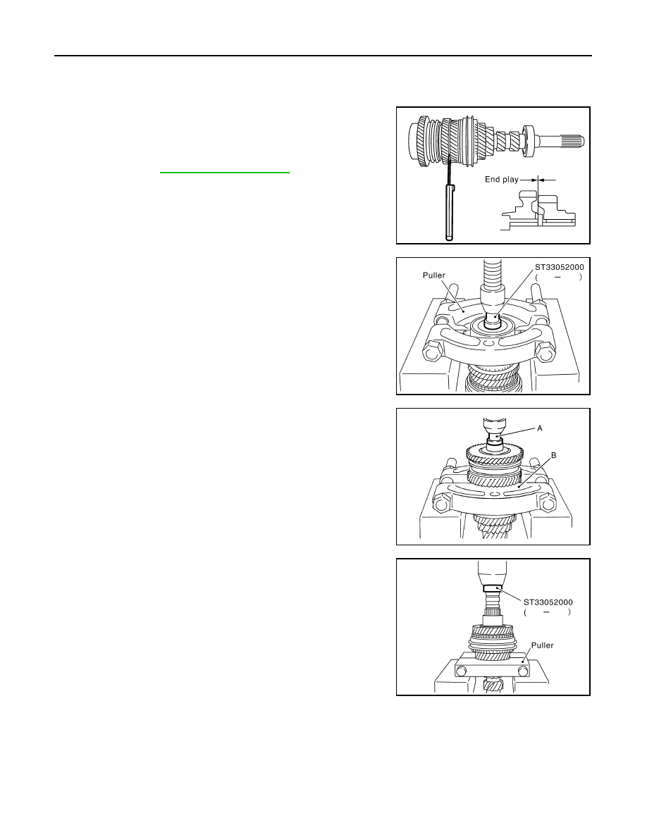
DISASSEMBLY

1. Before disassembling, measure end play for 3rd, 4th, 5th, and

6th input gears.

2. Remove oil channel.

3. Press out input shaft rear bearing using Tool and a puller.

4. Remove snap ring.

5. Press out 6th input gear, 6th needle bearing, 6th input gear

bushing, 5th-6th synchronizer hub assembly, and 5th input gear

using Tool (A) and a puller (B).

6. Remove 5th needle bearing.

7. Press out 5th input gear bushing, thrust washer, 4th input gear,

4th needle bearing, 4th input gear bushing, 3rd-4th synchronizer

hub assembly, and 3rd input gear using Tool and a puller.

8. Remove 3rd needle bearing.

End play standard value

: Refer to 

TM-144, "Gear End Play"

.

SCIA0966E

Tool number

: ST33052000 ( — )

SCIA1037E

Tool number

A: ST33052000 ( — )

PCIB1882E

Tool number

: ST33052000 ( — )

SCIA1030E

INPUT SHAFT AND GEARS

TM-119

< UNIT DISASSEMBLY AND ASSEMBLY >

[6MT: RS6F52H]

C

E

F

G

H

I

J

K

L

M

A

B

TM

N

O

P

9. Press out input shaft front bearing using a puller.

INSPECTION AFTER DISASSEMBLY

Input Shaft and Gears

Check items below. If necessary, replace them with new ones.

• Damage, peeling, dent, uneven wear, bending, etc. of shaft

• Excessive wear, damage, peeling, etc. of gears

Synchronizer

Check items below. If necessary, replace them with new ones.

• Damage and excessive wear of contact surfaces of coupling

sleeve, synchronizer hub and shifting insert

• Coupling sleeve and synchronizer hub must move smoothly.

• If any crack, damage, or excessive wear is found on cam face of

baulk ring or working face of insert, replace it.

BAULK RING CLEARANCE

• Single-cone synchronizer (4th, 5th, and 6th)

SCIA0920E

SCIA1074J

SMT387A

SMT867D

TM-120

< UNIT DISASSEMBLY AND ASSEMBLY >

[6MT: RS6F52H]

INPUT SHAFT AND GEARS

Push baulk ring on the cone and measure the clearance between

baulk ring and cone. If measurement is below limit, replace it with a

new one.

• Double-cone synchronizer (3rd)

Check the clearance between outer baulk ring, synchronizer cone,

and inner baulk ring as follows.

CAUTION:

The clearances (A) and (B) are controlled with outer baulk

ring, synchronizer cone, and inner baulk ring as a set.

Replace them as a set if the clearances are outside the limit

value.

1. Measure the clearance (A) at 2 points or more diagonally oppo-

site using a dial indicator. And then calculate mean value.

2. Measure the clearance (B) at 2 points or more diagonally oppo-

site using a feeler gauge. And then calculate mean value.

Bearing

Clearance

Standard value : Refer to 

TM-144, "Baulk Ring Clear-

ance"

.

Limit value

: Refer to 

TM-144, "Baulk Ring Clear-

ance"

.

SMT140

SCIA0950E

Tool number

: ST30031000 (J-22912-01)

Clearance (A)

Standard value : Refer to 

TM-144, "Baulk Ring Clear-

ance"

.

Limit value

: Refer to 

TM-144, "Baulk Ring Clear-

ance"

.

PCIB0945E

Clearance (B)

Standard value : Refer to 

TM-144, "Baulk Ring 

Clearance"

.

Limit value

: Refer to 

TM-144, "Baulk Ring 

Clearance"

.

SCIA1084E

INPUT SHAFT AND GEARS

TM-121

< UNIT DISASSEMBLY AND ASSEMBLY >

[6MT: RS6F52H]

C

E

F

G

H

I

J

K

L

M

A

B

TM

N

O

P

Check items below. If necessary, replace them with new ones.

• Damage and rough rotation of bearing

ASSEMBLY

1. Install 3rd needle bearing to input shaft.
2. Install 3rd input gear, 3rd inner baulk ring, 3rd synchronizer cone, and 3rd outer baulk ring to input shaft.

CAUTION:

Replace 3rd inner baulk ring, 3rd synchronizer cone, and 3rd outer baulk ring as a set.

3. Install 3rd-4th spread springs, 3rd-4th shifting inserts, and 3rd-4th synchronizer hub onto 3rd-4th coupling

sleeve.

CAUTION:

• Be careful with orientation of 3rd-4th synchronizer hub.

• Do not reuse 3rd-4th synchronizer hub and 3rd-4th cou-

pling sleeve.

• Replace 3rd-4th synchronizer hub and 3rd-4th coupling

sleeve as a set.

• Be careful with orientation of 3rd-4th coupling sleeve.

• Be sure not to hook center projection of 2 spread springs

on same shifting insert.

MTF0041D

SCIA0921E

PCIB0799E

SCIA1083E


Content   ..  1230  1231  1232  1233   ..