Content .. 1229 1230 1231 1232 ..
Nissan Juke F15. Manual - part 1231
TM-114
< UNIT DISASSEMBLY AND ASSEMBLY >
[6MT: RS6F52H]
TRANSAXLE ASSEMBLY
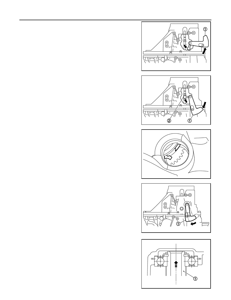
c.
With shifter lever A (1) held in the position shown, temporarily
assemble transaxle case to clutch housing.
CAUTION:
Do not damage striking rod oil seal.
NOTE:
Make sure to hold shifter lever A in the position shown. Other-
wise transaxle case cannot be installed to clutch housing.
d. While rotating shifter lever A (1) in the direction of the arrow
shown, assemble transaxle case to clutch housing.
e. Accessing from the bore plug hole, expand snap ring at main-
shaft rear bearing so that the ring catches the periphery of main-
shaft rear bearing.
f.
Temporarily tighten transaxle case bolts.
2. Shift the shifter lever A to 2nd gear position.
NOTE:
• The 2nd gear position is attained when shifter lever A (1) is in
the position shown.
• When transaxle is shifted to the 2nd gear position, mainshaft
assembly (1) is lifted.
PCIB1808E
2
: shifter lever B
PCIB1929E
PCIB1840E
PCIB1809E
PCIB1923E