Content .. 1227 1228 1229 1230 ..
Nissan Juke F15. Manual - part 1229
TM-106
< UNIT DISASSEMBLY AND ASSEMBLY >
[6MT: RS6F52H]
TRANSAXLE ASSEMBLY
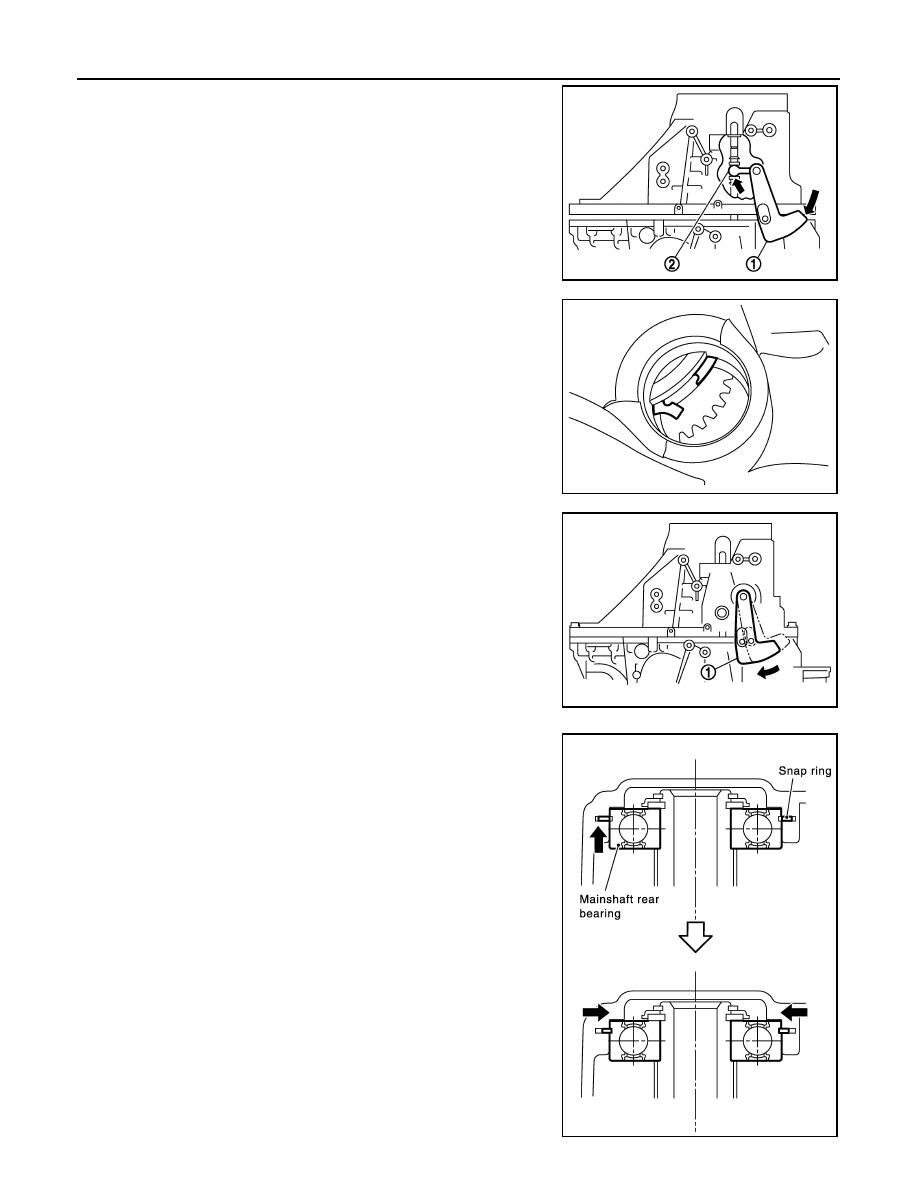
f.
While rotating shifter lever A (1) in the direction of the arrow
shown, assemble transaxle case to clutch housing.
g. Accessing from the bore plug hole, expand snap ring at main-
shaft rear bearing so that the ring catches the periphery of main-
shaft rear bearing.
h. Temporarily tighten transaxle case bolts.
i.
Shift the shifter lever A (1) to 2nd gear position.
NOTE:
• The 2nd gear position is attained when shifter lever A is in the
position shown.
• When transaxle is shifted to the 2nd gear position, mainshaft
assembly is lifted.
j.
Seat snap ring in the groove on mainshaft rear bearing. If snap
ring is not seated in the groove on mainshaft rear bearing,
remove transaxle case and repeat the procedure from step d.
2
: shifter lever B
PCIB1929E
PCIB1840E
PCIB1809E
SCIA0893E