Nissan Juke F15. Manual - part 1208


  Index      Nissan     Nissan Juke F15 (2015 year) - Service and Repair Manual


Search            


Content   ..  1206  1207  1208  1209   ..


Nissan Juke F15. Manual - part 1208


TM-22

< PERIODIC MAINTENANCE >

[6MT: RS6F94R]

GEAR OIL

PERIODIC MAINTENANCE

GEAR OIL

Inspection

INFOID:0000000012200760

OIL LEAKAGE

Make sure that gear oil is not leaking from transaxle or around it.
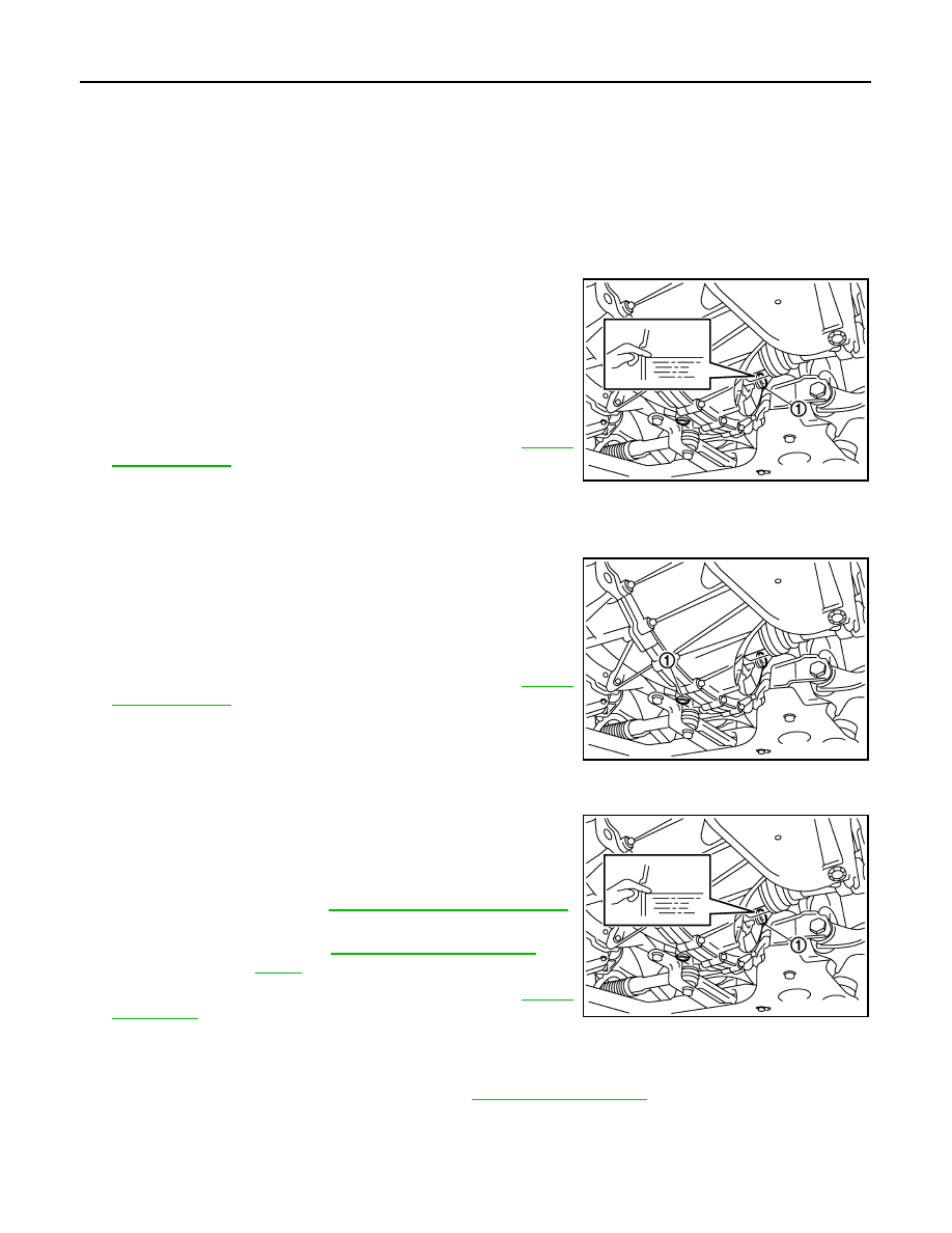
OIL LEVEL

1. Remove filler plug (1) and gasket from transaxle case.
2. Check the oil level from filler plug mounting hole as shown in the

figure.

CAUTION:

Never start engine while checking oil level.

3. Set a gasket on filler plug and then install it to transaxle case.

CAUTION:

Never reuse gasket.

4. Tighten filler plug to the specified torque. Refer to 

TM-32,

"Exploded View"

.

Draining

INFOID:0000000012200761

1. Start engine and let it run to warm up transaxle.
2. Stop engine. Remove drain plug (1) and gasket, using a socket

[Commercial service tool] and then drain gear oil.

3. Set a gasket on drain plug and install it to clutch housing, using

a socket [Commercial service tool].

CAUTION:

Never reuse gasket.

4. Tighten drain plug to the specified torque. Refer to 

TM-32,

"Exploded View"

.

Refilling

INFOID:0000000012200762

1. Remove filler plug (1) and gasket from transaxle case. 
2. Fill with new gear oil until oil level reaches the specified limit at

filler plug mounting hole as shown in the figure.

3. After refilling gear oil, check the oil level. Refer to 

TM-22,

"Inspection"

.

4. Set a gasket on filler plug and then install it to transaxle case.

CAUTION:

Never reuse gasket.

5. Tighten filler plug to the specified torque. Refer to 

TM-32, "Exploded View"

.

SCIA7623E

SCIA7622E

Oil grade and 
viscosity

: Refer to 

MA-11, "Fluids and Lubricants"

.

Oil capacity

: Refer to 

TM-67, "General Specifica-

tions"

.

SCIA7623E

SIDE OIL SEAL

TM-23

< REMOVAL AND INSTALLATION >

[6MT: RS6F94R]

C

E

F

G

H

I

J

K

L

M

A

B

TM

N

O

P

REMOVAL AND INSTALLATION

SIDE OIL SEAL

Removal and Installation

INFOID:0000000012200763

REMOVAL

1. Remove front drive shafts. Refer to 

FAX-83, "2WD : Removal and Installation"

.

2. Remove differential side oil seals (1) from clutch housing and

transaxle case, using an oil seal remover.

CAUTION:

Never damage transaxle case and clutch housing.

INSTALLATION

Note the following, and install in the reverse order of removal.

• Install differential side oil seals (1) to clutch housing and transaxle

case, using the drift [Stamping number: B.vi 1666-B] of the drift set

[SST: KV32500QAA ( - )].

CAUTION:

• Never incline differential side oil seal.

• Never damage clutch housing and transaxle case.

Inspection

INFOID:0000000012200764

INSPECTION AFTER INSTALLATION

Check the oil level and oil leakage. Refer to 

TM-22, "Inspection"

.

SCIA7625E

A

: Transaxle case side

B

: Clutch housing side

Dimension “L

1

: 1.2 – 1.8 mm (0.047 – 0.071 in)

Dimension “L

2

: 2.7 – 3.3 mm (0.106 – 0.130 in)

JPDIC0454ZZ

TM-24

< REMOVAL AND INSTALLATION >

[6MT: RS6F94R]

POSITION SWITCH

POSITION SWITCH

Removal and Installation

INFOID:0000000012200765

REMOVAL

1. Remove battery. Refer to 

PG-105, "Removal and Installation"

.

2. Disconnect position switch connector.
3. Remove position switch from transaxle case.

INSTALLATION

1. Apply recommended sealant to threads of position switch.

• Use Genuine Silicone RTV or an equivalent. Refer to 

GI-22, "Recommended Chemical Products

and Sealants"

.

CAUTION:

Remove old sealant and oil adhering to threads.

2. Install position switch to transaxle case.
3. Tighten position switch to the specified torque. Refer to 

TM-32, "Exploded View"

.

4. For the next step and after, install in the reverse order of removal.

Inspection

INFOID:0000000012200766

INSPECTION AFTER INSTALLATION

• Check continuity between position switch terminals. Refer to 

TM-20, "BACK-UP LAMP SWITCH : Compo-

nent Inspection"

 (Back-up lamp switch) and 

TM-20, "PARK/NEUTRAL POSITION (PNP) SWITCH : Compo-

nent Inspection"

 (PNP switch).

• Check the oil leakage. Refer to 

TM-22, "Inspection"

.

CONTROL LINKAGE

TM-25

< REMOVAL AND INSTALLATION >

[6MT: RS6F94R]

C

E

F

G

H

I

J

K

L

M

A

B

TM

N

O

P

CONTROL LINKAGE

Exploded View

INFOID:0000000012200767

Removal and Installation

INFOID:0000000012200768

REMOVAL 

1. Shift the shifter lever to the neutral position.
2. Remove air cleaner case. Refer to 

EM-192, "Removal and Installation"

.

1.

Bracket

2.

Shifter cable

3.

Selector lever

4.

Shifter lever A

5.

Tapping bolt

6.

Cable mounting bracket

7.

Selector cable

8.

Grommet

9.

M/T shift selector assembly

10. Shifter lever

11. Shifter lever knob

 : Always replace after every disassembly.

 : N·m (kg-m, ft-lb)

 : N·m (kg-m, in-lb)

JPDIC0830GB


Content   ..  1206  1207  1208  1209   ..