Content .. 1156 1157 1158 1159 ..
Nissan Juke F15. Manual - part 1158
DIAGNOSIS SENSOR UNIT
SR-29
< REMOVAL AND INSTALLATION >
C
D
E
F
G
I
J
K
L
M
A
B
SR
N
O
P
DIAGNOSIS SENSOR UNIT
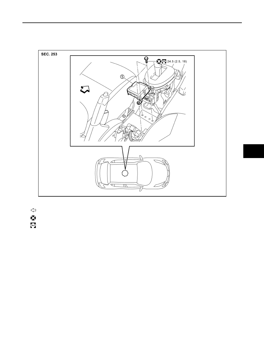
Exploded View
INFOID:0000000012199981
Removal and Installation
INFOID:0000000012199982
WARNING:
• Before servicing, turn ignition switch OFF, disconnect battery negative terminal and wait 3 minutes
or more.
• Before disconnecting the air bag sensor unit harness connector, be sure to disconnect the each har-
ness connector of the air bag module and pre-tensioner seat belt to prevent air bag deployment by
static electricity and pre-tensioner seat belt operation.
• Never use the air tools or electric tools for servicing.
• When replacing the air bag diagnosis sensor unit, always check with the parts department for the lat-
est parts information. Installing an incorrect air bag diagnosis sensor unit may or may not cause the
air bag warning lamp to illuminate and may cause incorrect deployment of the supplemental air bags
and seat belt pre-tensioners in a collision resulting in serious personal injury or death.
REMOVAL
1. Always check the air bag diagnosis sensor unit ECU discriminated number (identification number) using
CONSULT.
2. Disconnect the each connector of all air bag modules and pre-tensioner seat belts.
1.
Diagnosis sensor unit
: Vehicle front
: Always replace after every disassembly.
: N·m (kg-m, ft-lb)
JMHIA3047GB