Nissan Juke F15. Manual - part 23
AV-78
< SYSTEM DESCRIPTION >
[AUDIO WITH NAVIGATION]
DIAGNOSIS SYSTEM (NAVI CONTROL UNIT)
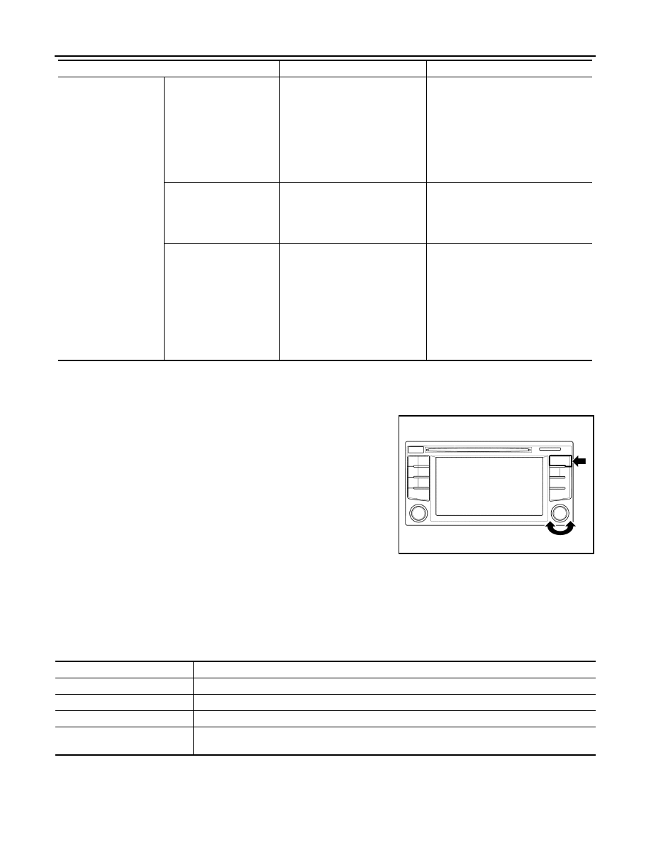
METHOD OF STARTING
1. Start the engine.
2. Turn OFF audio.
3. While pressing the “APPS·i” switch, turn the “+,
−” dial counter-
clockwise 3 clicks or more first, then clockwise and counter-
clockwise 3 clicks or more, respectively. (After the diagnosis
mode starts, the initial screen of the diagnosis mode appears.)
END ON-BOARD DIAGNOSIS
Turn OFF ignition switch.
CONSULT Function
INFOID:0000000012202499
CONSULT FUNCTIONS
CONSULT performs the following functions via communication with the NAVI control unit.
ECU IDENTIFICATION
The part number of NAVI control unit is displayed.
SELF DIAGNOSTIC RESULT
Test function
System self test
• Bluetooth MODULE Access
Malfunction
• SD-card Access Malfunction
• Radio-Antenna Circuit Malfunc-
tion
• SXM Antenna Circuit Malfunc-
tion
• GPS Antenna Circuit Malfunc-
tion
A system self test is executed: the result
is stored into the error memory which is
shown afterwards as a list of codes of
the detected malfunctions.
Speaker test
—
This activates a sequence of test tone
outputs to the four speaker lines one af-
ter the other for 1 second. The frequen-
cy can be chosen by user selection
before (100 Hz and 4000 Hz).
Display test
—
This provides a test sequence where
test displays (plain colored display: e.g.
white, black, red, blue, green) are
shown one after the other. The respec-
tive color is shown for an indicated peri-
od of time (parameter). After the display
test, the design of the display previously
available is stored. While the screen
shows a plain colored display, a pixel
malfunction may be detected.
Mode
Item
Content
JSNIA7266ZZ
Direct Diagnostic Mode
Description
Ecu Identification
The NAVI control unit part number is displayed.
Self Diagnostic Result
The NAVI control unit self diagnostic results are displayed.
Data Monitor
The NAVI control unit input/output data is displayed in real time.
Configuration
• The vehicle specification can be read and saved.
• The vehicle specification can be written when replacing NAVI control unit.