Nissan Juke F15. Manual - part 22
AV-74
< SYSTEM DESCRIPTION >
[AUDIO WITH NAVIGATION]
SYSTEM
Camera Image Operation Principle
• If the camera image calibration is incomplete, the applicable camera position is indicated as an error on the
Birds-Eye view display. (Calibration operation is necessary when replacing each camera or when replacing
around view monitor control unit.)
• Around view monitor control unit receives the camera switch signal via CAN communication from NAVI con-
trol unit by pressing the “CAMERA” switch.
• Around view monitor control unit that receives the camera switch signal supplies the power to each camera
and inputs the camera image from each camera.
• When the selector lever is in the reverse position, around view monitor control unit receives the reverse sig-
nal, supplies the power to each camera, and inputs the camera image from each camera.
• Around view monitor control unit that receives the camera image signal from each camera cuts out the
required screen for each view, superimposes the camera image, vehicle icon, guiding lines, and outputs
them to the NAVI control unit.
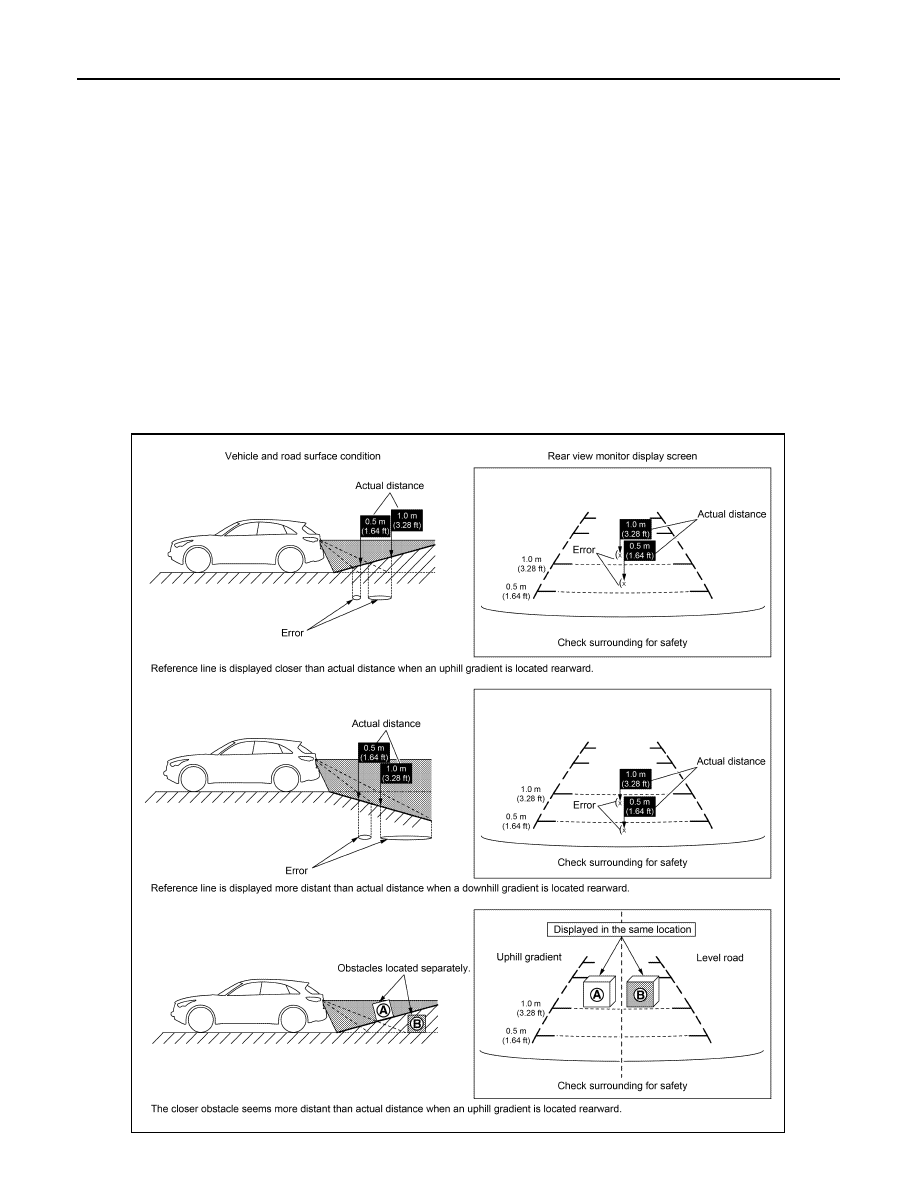
Precautions for Vehicle Width Guide Line and Predictive Course Line Display on The Rear View Monitor Display
Side distance guide lines and predictive course line on the display may be different from actual lines depend-
ing on vehicle conditions and road conditions.
PRECAUTIONS FOR ROAD CONDITIONS
• Since guide lines and predictive course line are drawn based on the road, a different distance may be dis-
played if a protruding block is present nearby.
JSNIA8941GB