Nissan Juke F15. Manual - part 20
AV-66
< SYSTEM DESCRIPTION >
[AUDIO WITH NAVIGATION]
SYSTEM
SYSTEM
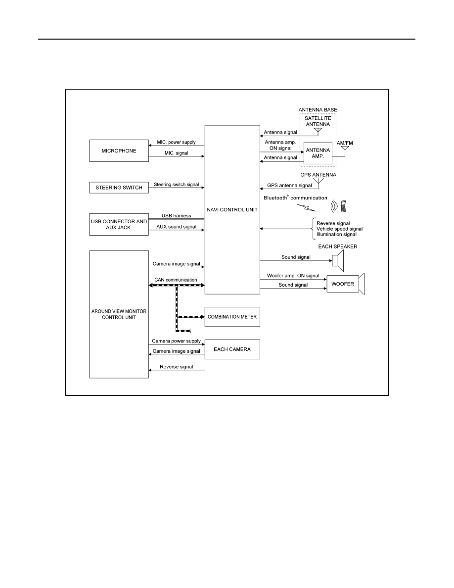
System Description
INFOID:0000000012202496
SYSTEM DIAGRAM
DESCRIPTION
Refer to Owner’s Manual for navigation and audio system operating instructions.
Audio function and display are built into NAVI control unit.
This navigation has the following functions.
• Map data on SD card.
• Full support for playback of music from iPod
®
, iPhone, and USB device.
• High resolution full color touch panel 5.8 inch “QVGA” display.
• FM/AM digital tuner.
• USB mass storage connection.
• Satellite radio.
• Bluetooth
®
audio streaming.
• RDS
• POI Support is included. User POI download.
• Hands-free phone system.
• Around view monitor function.
iPod
®
is a trademark of Apple inc., registered in the U.S. and other countries.
NAVIGATION SYSTEM FUNCTION
JSNIA8053GB