содержание .. 791 792 793 794 ..
Nissan Tiida C11. Manual - part 793
FUEL TANK
FL-11
< ON-VEHICLE REPAIR >
C
D
E
F
G
H
I
J
K
L
M
A
FL
N
P
O
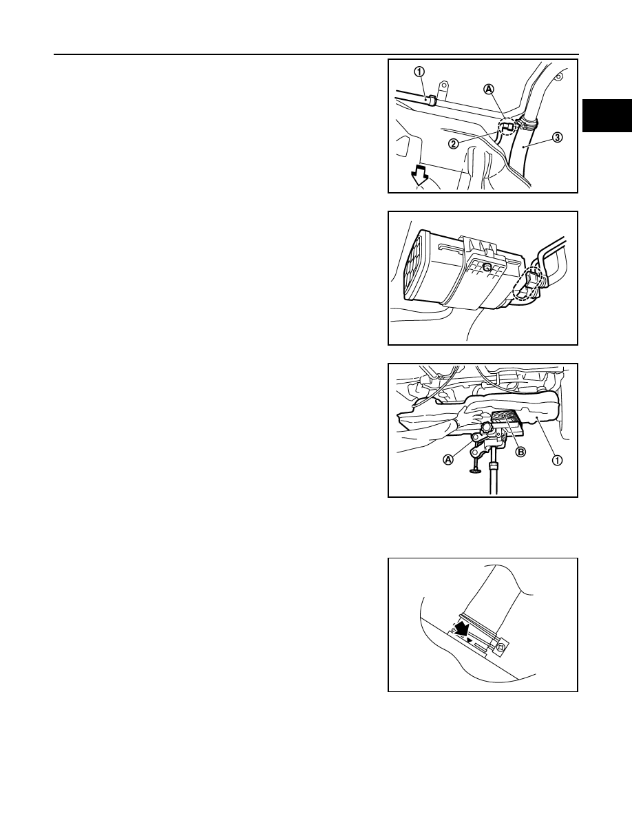
6.
Disconnect EVAP tube (2) at rear side of fuel tank.
• Vent hose (1)
•
⇐
: Vehicle front
7.
Remove fuel filler hose (3) at fuel filler tube side.
8.
If necessary, remove mounting screw and quick connectors and
slide the EVAP canister rearward to remove it from the fuel tank.
9.
Support center of fuel tank (1) with transmission jack (A).
10. Remove fuel tank straps (RH and LH).
11. Lower transmission jack carefully to remove fuel tank while sup-
porting it by hand.
CAUTION:
Fuel tank may be in an unstable position because of the
shape of fuel tank bottom. Be sure to support tank securely.
INSTALLATION
Note the following, and install in the reverse order of removal.
Fuel Filler Hose
• Install fuel filler hose to fuel tank, paying attention to install
mark.Marking faces downward
JPBIA0456ZZ
MBIB9040E
PBIC3792E
MBIB9043E