содержание .. 790 791 792 793 ..
Nissan Tiida C11. Manual - part 792
FUEL LEVEL SENSOR UNIT, FUEL FILTER AND FUEL PUMP ASSEMBLY
FL-7
< ON-VEHICLE REPAIR >
C
D
E
F
G
H
I
J
K
L
M
A
FL
N
P
O
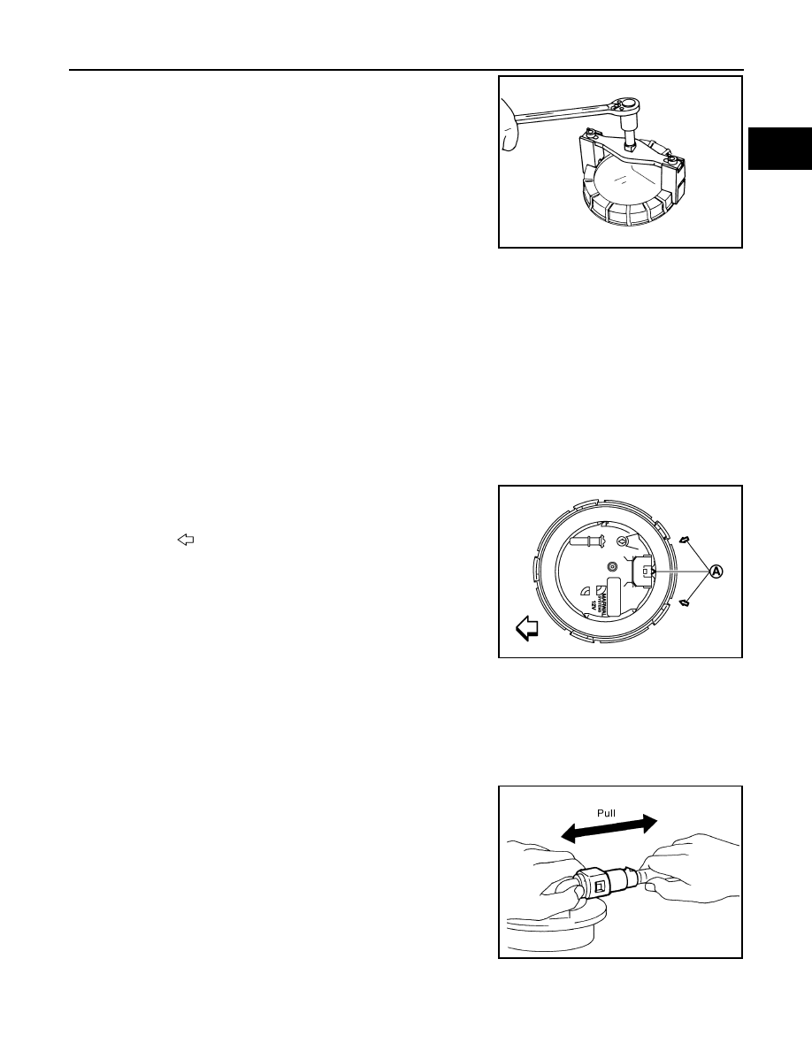
8.
Remove the lock ring using tool as shown.
9.
Remove fuel level sensor unit, fuel filter and fuel pump assembly (1).
CAUTION:
• Do not bend float arm during removal.
• Do not allow foreign materials to fall into fuel tank. Use a lint free cloth when handling compo-
nents.
• Avoid impacts such as dropping when handling components.
INSPECTION AFTER REMOVAL
Make sure that the fuel level sensor unit, fuel filter and fuel pump is free from defects and foreign materials.
INSTALLATION
Installation is in the reverse order of removal.
Fuel Level Sensor Unit, Fuel Filter and Fuel Pump Assembly
1.
Install O-ring to fuel tank without twisting.
2.
Install fuel level sensor unit with aligning mating marks (A) on
fuel tank and fuel level sensor unit as shown.
Quick Connector
Connect fuel feed tube quick connector using the following procedure.
1.
Check the connection for damage or any foreign materials.
2.
Align the connector with the tube, then insert the connector straight into the tube until a “click” sound is
heard.
3.
After connecting, make sure that the connection is secure using the following procedure.
• Visually confirm that the two retainer tabs are secured to the connector.
• Pull the tube and the connector to make sure they are securely
connected.
4.
Connect electrical harness connector.
Inspection Hole Cover
PBIC0240E
: Vehicle front
PBIC4732E
PBIC1653E