Nissan Tiida C11. Manual - part 791


  Главная      Nissan     Nissan Tiida C11 - Service Manual


поиск по сайту            


содержание   ..  789  790  791  792   ..


Nissan Tiida C11. Manual - part 791


PREPARATION

FL-3

< PREPARATION >

C

D

E

F

G

H

I

J

K

L

M

A

FL

N

P

O

PREPARATION

PREPARATION

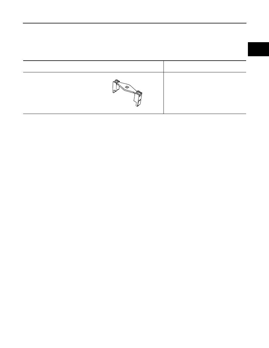
Special Service Tool

INFOID:0000000001722974

Tool number
Tool name

Description

KV993G0010
(MOT. 1397)
Lock ring wrench

Removing and installing lock ring

ZZA0122D

FL-4

< ON-VEHICLE MAINTENANCE >

FUEL SYSTEM

ON-VEHICLE MAINTENANCE

FUEL SYSTEM

Checking Fuel Line

INFOID:0000000001722976

Inspect fuel lines, fuel filler cap and fuel tank for improper attach-
ment, leaks, cracks, damage, loose connections, chafing or deterio-
ration.
If necessary, repair or replace damaged parts.

General Precaution

INFOID:0000000001722977

WARNING:

When replacing fuel line parts, be sure to observe the following.
• Put a “CAUTION: FLAMMABLE” sign in the work area.
• Be sure to work in a well ventilated area and have a CO

2

 fire extinguisher. 

• Do not smoke while working on the fuel system. Keep open flames and sparks away from the work

area.

• Put drained fuel in an explosion-proof container and put the lid on securely. Keep the container in

safe area.

CAUTION:

• Use gasoline required by the regulations for octane number. Refer to 

GI-45, "Precaution for Fuel

(Unleaded Regular Gasoline Recommended)"

.

• Before removing fuel line parts, perform the following procedures:
- Release fuel pressure from the fuel lines if necessary. Refer to 

EC-379, "Inspection"

 (HR16DE with

Euro-OBD), 

EC-681, "Inspection"

 (HR16DE without Euro-OBD), 

EC-1035, "Inspection"

 (MR18DE). 

- Disconnect the battery ground cable. 
• Always replace O-rings and clamps with new ones.
• Do not kink or twist tubes when they are being installed.
• Perform work on level surface.
• Do not tighten hose clamps excessively to avoid damaging hoses. 
• After connecting fuel tube quick connectors, make sure quick connectors are secure.

Ensure that connector and resin tube do not contact any adjacent parts.

• After installing tubes, make sure there is no fuel leakage at connections in the following steps.
- Apply fuel pressure to fuel lines by turning ignition switch ON (without starting the engine). Then

check for fuel leaks at the fuel tube connections.

- Start engine and rev it up and check for fuel leaks at connections.
• Use only a genuine NISSAN fuel filler cap as a replacement. If an incorrect fuel filler cap is used, the

MIL may come on. 

• For servicing “Evaporative Emission System” parts, refer to 

EC-379, "Inspection"

 (HR16DE with

Euro-OBD), 

EC-683, "Inspection"

 (HR16DE without Euro-OBD), 

EC-1037, "Inspection"

 (MR18DE).

SMA803A

FUEL LEVEL SENSOR UNIT, FUEL FILTER AND FUEL PUMP ASSEMBLY

FL-5

< ON-VEHICLE REPAIR >

C

D

E

F

G

H

I

J

K

L

M

A

FL

N

P

O

ON-VEHICLE REPAIR

FUEL LEVEL SENSOR UNIT, FUEL FILTER AND FUEL PUMP ASSEMBLY

HR16DE, HR18DE

INFOID:0000000001723038

Exploded View

INFOID:0000000001723039

Removal and Installation

INFOID:0000000001722979

REMOVAL

WARNING:

Be sure to read “General Precautions” before working on the fuel system. Refer to 

FL-4, "General Pre-

caution"

.

1.

Check fuel level with the vehicle on a level surface. If the fuel
gauge indicates more than the level in the figure (full or almost
full), drain fuel from the fuel tank until the fuel gauge indicates
level as shown in the figure or below.
NOTE:
Fuel will be spilled when removing fuel pump assembly if fuel
level is above the fuel pump assembly installation surface. 
• As a guide, fuel level is at the level as shown or below when

approximately 15   (3-1/4 Imp gal) of fuel is drained from fuel
tank. 

• In case fuel pump does not operate, perform the following pro-

cedure.

a.

Insert fuel tubing of less than 20 mm (0.79 in) in diameter into fuel filler tube through fuel filler opening to
drain fuel from fuel filler tube.

1.

Lock ring

2.

Fuel level sensor unit, fuel filter and fuel pump assembly

3.

O-ring

4.

Fuel tank

Front

JPBIA0300GB

JPBIA0459ZZ

FL-6

< ON-VEHICLE REPAIR >

FUEL LEVEL SENSOR UNIT, FUEL FILTER AND FUEL PUMP ASSEMBLY

b.

Disconnect fuel filler hose from fuel filler tube. Refer to 

FL-10, "HR16DE, HR18DE"

.

c.

Insert fuel tubing into fuel tank through fuel filler hose to drain fuel from fuel tank.

2.

Release the fuel pressure from the fuel lines. Refer to 

EC-377, "Inspection"

 (HR16DE with EURO-OBD),

EC-681, "Inspection"

 (HR16DE without EURO-OBD), 

EC-1035, "Inspection"

 (MR18DE).

3.

Open fuel filler lid.

4.

Open fuel door and unscrew the fuel filler cap to release the pressure inside the fuel tank.

5.

Remove rear seat bottom. Refer to 

SE-18, "Removal and Installation"

.

6.

Turn the four retainers 90

°

 in a clockwise direction and remove the fuel pump inspection hole cover.

7.

Disconnect electrical connector (A) and fuel feed hose quick
connector (B).

 : Vehicle front

• Disconnect the quick connector using the following procedure.

- Hold the sides of the connector, push in tabs and pull out the

tube. 

- If quick connector and tube on fuel pump assembly are stuck,

push and pull several times until they move. Disconnect them
by pulling.

CAUTION:

• The tube can be removed when the tabs are completely

depressed. Do not twist it more than necessary.

• Do not use any tools to remove the quick connector.
• Keep resin tube away from heat. Be especially careful

when welding near the resin tube.

• Prevent acid liquid such as battery electrolyte, from get-

ting on resin tube.

• Do not bend or twist resin tube during installation and removal. 
• To keep the connecting portion clean, free of foreign

materials and to avoid damage, cover them completely
with plastic bags or something similar.      

• Do not insert plug to prevent damage to O-ring in quick

connector.

JPBIA0457ZZ

SFE562A

PBIC0163E


содержание   ..  789  790  791  792   ..