содержание .. 787 788 789 790 ..
Nissan Tiida C11. Manual - part 789
FRONT DRIVE SHAFT
FAX-21
< DISASSEMBLY AND ASSEMBLY >
C
E
F
G
H
I
J
K
L
M
A
B
FAX
N
O
P
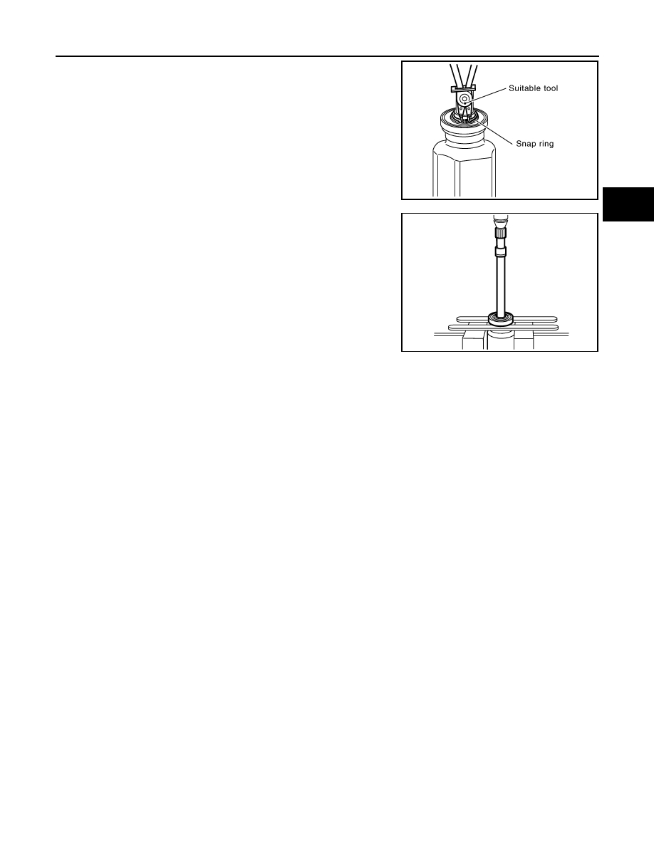
2.
Remove dust shield, then remove snap ring using a suitable
tool.
3.
Press support bearing assembly off slide joint assembly using a
suitable tool.
4.
Remove dust shield.
Damper
• Remove damper bands, then remove damper from shaft.
INSPECTION AFTER DISASSEMBLY
Shaft
Replace shaft if there is bending, cracking, or other damage.
Joint Sub-Assembly
• Make sure there is no rough rotation or unusual axial looseness.
• Make sure there is no foreign material inside joint sub-assembly.
• Check joint sub-assembly for compression scars, cracks or fractures.
CAUTION:
If there are any irregular conditions of joint sub-assembly components, replace the entire joint sub-
assembly.
Slide Joint Housing and Spider Assembly
Make sure there are no compression scars, cracks, fractures or unusual wear of housing or spider roller con-
tact surface.
CAUTION:
If there are any irregular conditions of the slide joint housing and spider assembly components,
replace them as a set.
Support Bearing
Make sure wheel bearing rolls freely and is free from noise, cracks, pitting or wear.
Support Bearing Bracket
Check for bending, cracks, or damage.
Damper
Check damper for cracks or wear. Replace as necessary.
ASSEMBLY
Transaxle Side
YAX003
YAX004