содержание .. 786 787 788 789 ..
Nissan Tiida C11. Manual - part 788
FRONT DRIVE SHAFT
FAX-17
< DISASSEMBLY AND ASSEMBLY >
C
E
F
G
H
I
J
K
L
M
A
B
FAX
N
O
P
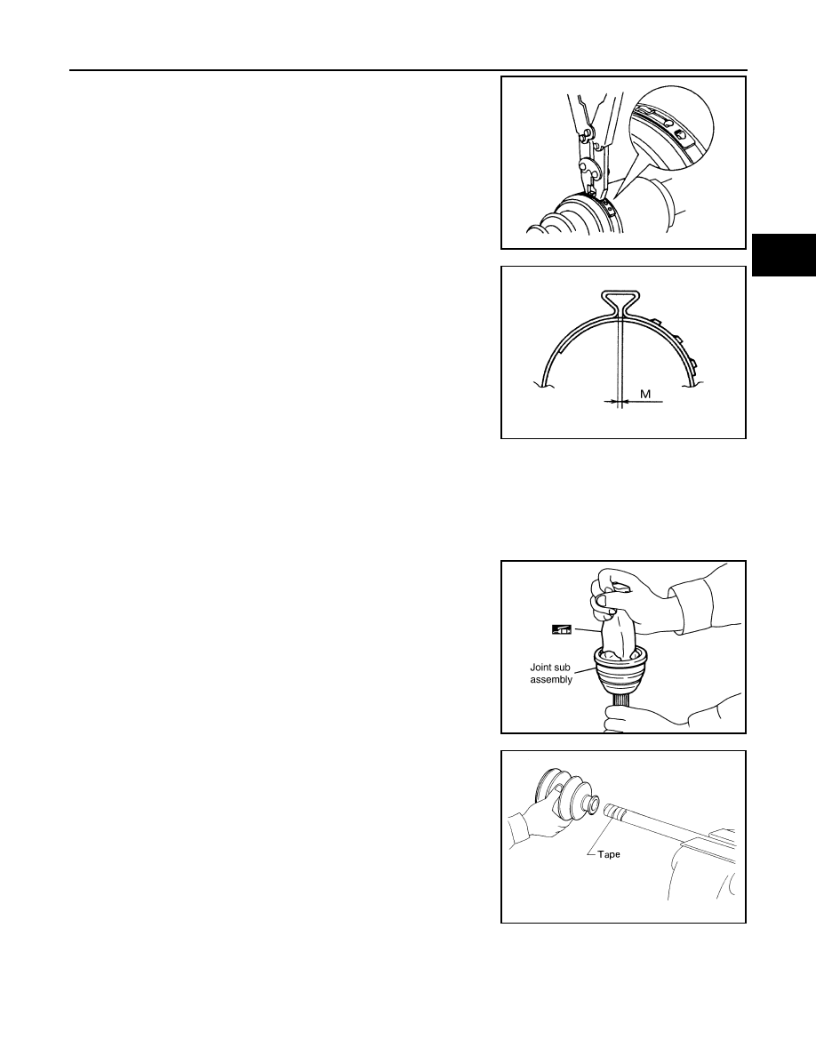
2.
Pull and tighten the boot band using suitable tool until both
pawls of boot band are secured in the boot band grooves.
CAUTION:
Do not reuse boot band.
10. Install new small boot band securely using Tool.
CAUTION:
• Do not reuse boot band.
• Secure boot band so that dimension “M” meets specifica-
tion as shown.
11. Rotate the slide joint and confirm that the boot position is correct. If boot position is not correct, remove
the boot bands, reposition the boot and install new boot bands.
12. Install new dust shield to slide joint housing.
CAUTION:
Do not reuse dust shield.
Wheel Side
1.
Insert recommended grease (Genuine NISSAN Grease or
equivalent) into joint sub-assembly serration hole until grease
begins to ooze from ball groove and serration hole. After insert-
ing grease, use a shop cloth to wipe off old grease that has
oozed out.
2.
Cover serrated part of shaft with tape. Install new boot band and
new boot to shaft.
CAUTION:
Do not reuse boot or boot band.
3.
Remove protective tape wound around serrated part of shaft.
RAC1133D
Tool number
: KV40107300 (
—
)
Dimension “M”
: 1.0 – 4.0 mm (0.039 – 0.157 in)
DSF0047D
SDIA1127E
SFA800