содержание .. 792 793 794 795 ..
Nissan Tiida C11. Manual - part 794
FUEL TANK
FL-15
< ON-VEHICLE REPAIR >
C
D
E
F
G
H
I
J
K
L
M
A
FL
N
P
O
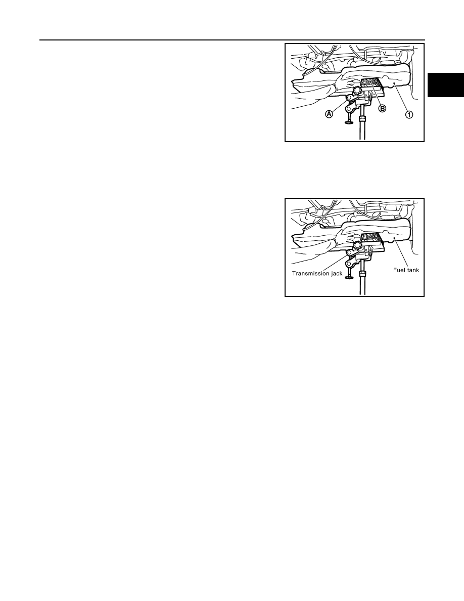
9.
Support center of fuel tank (1) with transmission jack (A).
CAUTION:
Securely support the fuel tank with a suitable tool (B).
10. Remove fuel tank mounting straps.
11. Lower transmission jack carefully to remove fuel tank while sup-
porting it by hand. Perform the following works at the same time.
• Pull out vent hose from through hole of vehicle.
• Avoid interference with tank by pulling parking brake cable by
hand.
CAUTION:
Fuel tank may be in an unstable position because of the
shape of fuel tank bottom. Be sure to support tank securely.
INSTALLATION
Installation is in the reverse order of removal.
EVAP Hose
1.
Check connections for damage or foreign material.
2.
Align the mating side connection part with the center of shaft,
and insert connector straight until it clicks.
3.
After connecting, pull out quick connector by hand. Make sure
connections are secure.
Installation of Vent Hose
• Push vent hose into through hole of vehicle.
• Insert vent hose into vent rubber hose, and secure it with clamp.
Installation of Fuel Tank Mounting Strap
• Install them in the proper position by referring to the identification stamp mark “R” and “L1” on the end.
Fuel Filler Hose
• Insert fuel filler hose to the length below.
• When installing clamp, do not allow clamp to contact the bulge (bump) part of the tube.
• Tighten the clamp of filler hose.
INSPECTION AFTER INSTALLATION
Use the following procedure to check for fuel leaks.
1.
Turn ignition switch “ON” (without starting the engine), to check the connections for fuel leaks with the
electric fuel pump applying pressure to the fuel piping.
2.
Start the engine and let it idle to check that there are no fuel leaks at the fuel system connections.
PBIC3792E
PBIC1508E
: 35mm (1.38 in)
Filler hose clamp
: 2.5 N·m (0.26 kg-m, 22 in-lb)