содержание .. 733 734 735 736 ..
Nissan Tiida C11. Manual - part 735
EM-292
< ON-VEHICLE REPAIR >
[K9K]
TIMING BELT
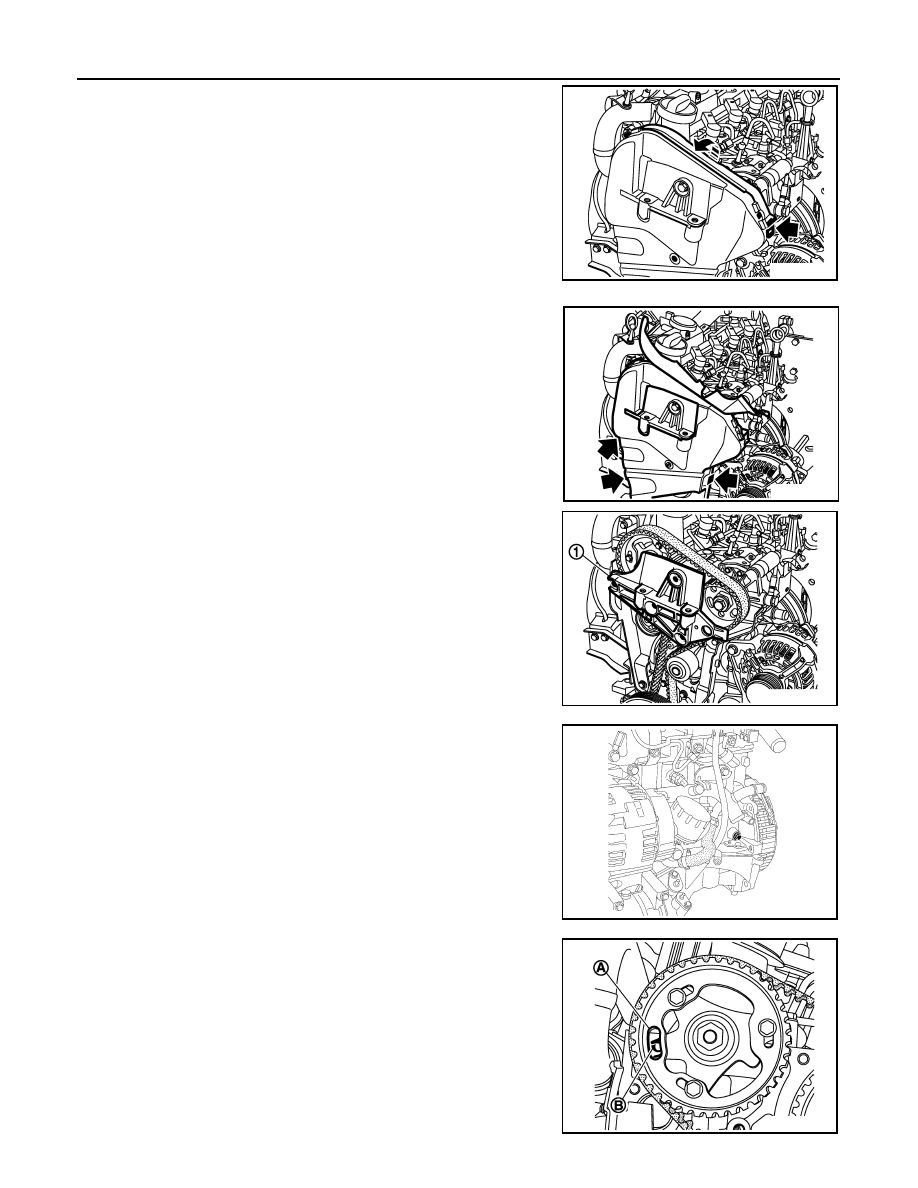
8.
Remove timing belt cover (upper).
9.
Remove cylinder head suspended mounting bracket (1).
10. Remove timing belt cover (lower).
11. Remove the TDC pin plug.
12. Rotate the crankshaft clockwise, until the position (A) of the
camshaft pulley is opposite of the position (B) on the cylinder
head.
E1BIA0040ZZ
E1BIA0041ZZ
E1BIA0042ZZ
MBIB0392E
E1BIA0043ZZ