содержание .. 683 684 685 686 ..
Nissan Tiida C11. Manual - part 685
EM-92
< REMOVAL AND INSTALLATION >
[HR16DE]
ENGINE ASSEMBLY
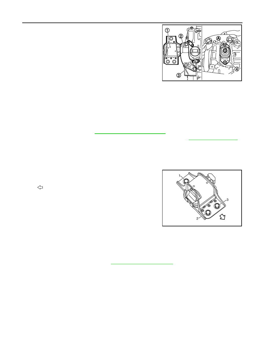
4.
Remove engine mounting insulator (RH) (1), engine mounting
bracket (RH) (2) and engine mounting stay (3).
5.
Remove engine mounting through bolt-securing nut (A).
6.
Carefully lower jack, or raise lift to remove the engine and the transaxle assembly.
CAUTION:
• Make sure that no part interferes with the vehicle side.
• Before and during this lifting, always check if any harnesses are left connected.
• During the removal, always be careful to prevent the vehicle from falling off the lift due to
changes in the center of gravity.
• If necessary, support the vehicle by setting jack or suitable tool at the rear.
Separation
1.
Remove starter motor. Refer to
STR-13, "Removal and Installation"
.
2.
Lift with a hoist and separate the engine from the transaxle assembly. Refer to
.
INSTALLATION
Installation is in the reverse order of removal.
• Do not allow engine oil to get on engine mounting insulator. Be careful not to damage engine mounting insu-
lator.
• Make sure that each mounting insulator is seated properly, and tighten mounting nuts and bolts.
• Tighten engine mounting insulator (RH) bolts in the numerical
order shown.
Inspection
INFOID:0000000001381426
INSPECTION AFTER INSTALLATION
Inspection for Leaks
• Before starting engine, check oil/fluid levels including engine coolant and engine oil. If less than required
quantity, fill to the specified level. Refer to
MA-19, "Fluids and Lubricants"
.
• Use procedure below to check for fuel leakage.
- Turn ignition switch “ON” (with engine stopped). With fuel pressure applied to fuel piping, check for fuel leak-
age at connection points.
- Start engine. With engine speed increased, check again for fuel leakage at connection points.
• Run engine to check for unusual noise and vibration.
• Warm up engine thoroughly to make sure there is no leakage of fuel, exhaust gases, or any oil/fluids includ-
ing engine oil and engine coolant.
• Bleed air from lines and hoses of applicable lines, such as in cooling system.
• After cooling down engine, again check oil/fluid levels including engine oil and engine coolant. Refill to the
specified level, if necessary.
4
: Engine mounting insulator (LH)
JPBIA0512ZZ
: Vehicle front
JPBIA0280ZZ