Nissan Tiida C11. Manual - part 684


  Главная      Nissan     Nissan Tiida C11 - Service Manual


поиск по сайту            


содержание   ..  682  683  684  685   ..


Nissan Tiida C11. Manual - part 684


EM-88

< ON-VEHICLE REPAIR >

[HR16DE]

CYLINDER HEAD

6.

Install valve spring.
NOTE:
It can be installed in either direction.

7.

Install valve spring retainer.

8.

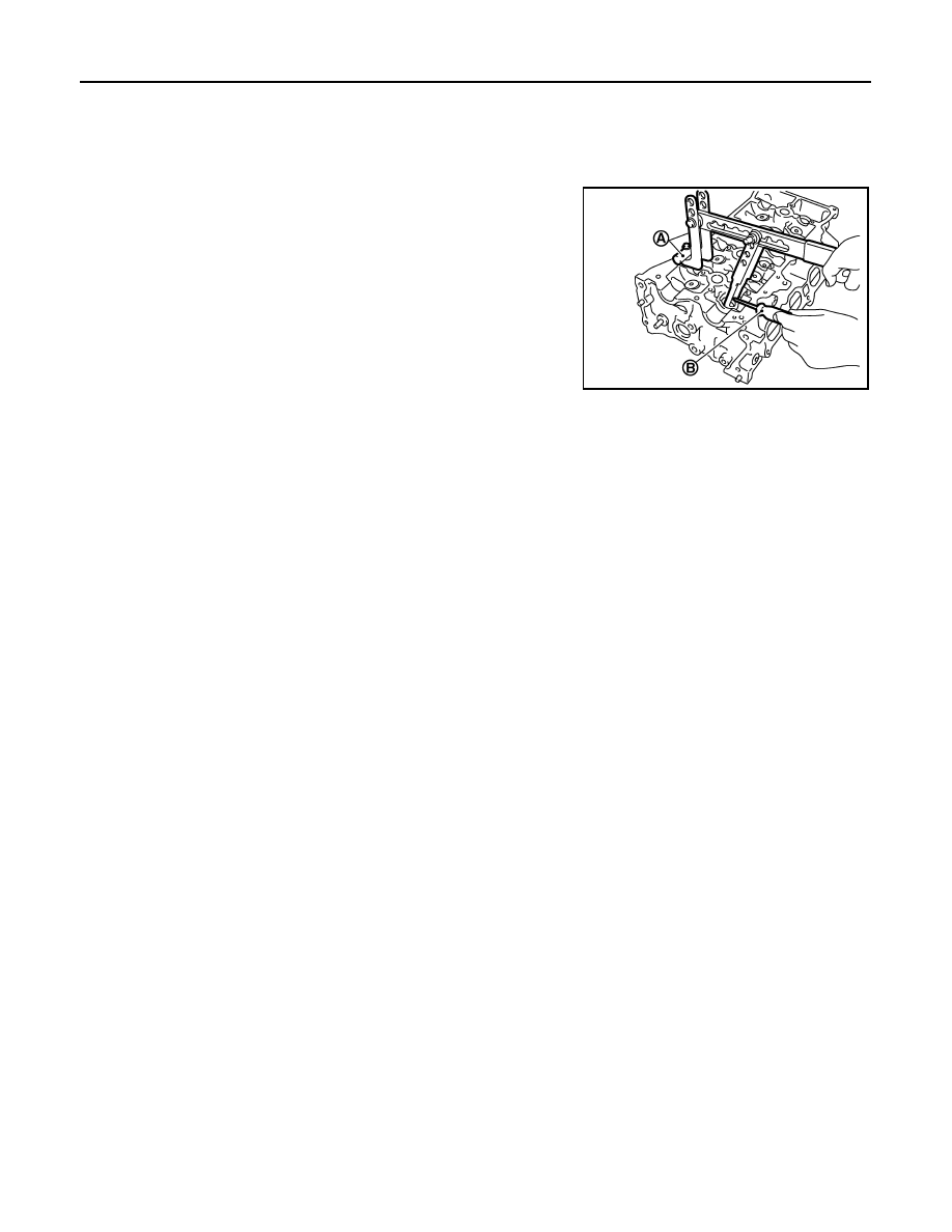
Install valve collet.
• Compress valve spring with the valve spring compressor, the

attachment and the adapter [SST: KV10116200] (A). Install
valve collet with a magnet hand (B).

CAUTION:

Be careful not to damage valve lifter holes.

• Tap valve stem edge lightly with a plastic hammer after instal-

lation to check its installed condition.

9.

Install valve lifter.

10. Install spark plug with a suitable tool.

PBIC3727E

ENGINE ASSEMBLY

EM-89

< REMOVAL AND INSTALLATION >

[HR16DE]

C

D

E

F

G

H

I

J

K

L

M

A

EM

N

P

O

REMOVAL AND INSTALLATION

ENGINE ASSEMBLY

Exploded View

INFOID:0000000001381424

Removal and Installation

INFOID:0000000001381425

WARNING:

• Situate the vehicle on a flat and solid surface.
• Place chocks at front and back of rear wheels.
• Attach proper slingers and bolts described in PARTS CATALOG if engine slingers are not equipped.

CAUTION:

• Always be careful to work safely, avoid forceful or uninstructed operations.
• Never start working until exhaust system and coolant are cool enough.

1.

Engine mounting insulator (LH)

2.

Engine mounting bracket (LH)

3.

Mass damper

4.

Dynamic damper

5.

Engine mounting insulator (RH)

6.

Engine mounting stay

7.

Engine mounting bracket (RH)

8.

Rear engine mounting bracket

9.

Rear torque rod

10.

Washer

11.

Engine mounting bracket (LH)

A.

Front mark

B.

M/T models

PBIC3736E

EM-90

< REMOVAL AND INSTALLATION >

[HR16DE]

ENGINE ASSEMBLY

• If items or work required are not covered by the engine section, follow the procedures in the applica-

ble sections.

• Always use the support point specified for lifting.
• Use either 2-pole lift type or separate type lift as best you can. If board-on type is used for unavoid-

able reasons, support at the rear axle jacking point with a transmission jack or similar tool before
starting work, in preparation for the backward shift of center of gravity.

• For supporting points for lifting and jacking point at rear axle, refer to 

GI-48, "Garage Jack and

Safety Stand and 2-Pole Lift"

.

REMOVAL

Outline

Remove the engine and the transaxle assembly from the vehicle downward. Separate the engine and the tran-
saxle.

Preparation

1.

Remove the hood assembly. Refer to 

DLK-214, "Removal and Installation"

.

2.

Remove the cowl top cover and cowl top extension assembly. Refer to 

EXT-20, "Removal and Installa-

tion"

.

3.

Release fuel pressure. Refer to 

EC-377, "Inspection"

 (EURO-OBD), 

EC-681, "Inspection"

 (WITHOUT

EURO-OBD).

4.

Drain engine coolant from radiator. Refer to 

CO-11, "Changing Engine Coolant"

.

CAUTION:

• Perform this step when the engine is cold.
• Never spill engine coolant on drive belt.

5.

Drain the transmission fluid. Refer to 

TM-628, "Draining"

 (M/T models), 

TM-171, "Changing A/T Fluid"

 (A/

T models).

6.

Remove the following parts.
• Engine undercover
• Front road wheels and tires: Refer to 

WT-6, "Rotation"

.

• Front fender protector (RH and LH): Refer to 

EXT-22, "Removal and Installation"

• Battery and battery tray: Refer to 

PG-6, "Removal and Installation"

.

• Drive belt: Refer to 

EM-16, "Removal and Installation"

.

• Air duct and air cleaner case assembly: Refer to 

EM-27, "Exploded View"

.

• Radiator hose (upper and lower): Refer to 

CO-16, "Component"

.

• Disconnect cooling fan controller wiring harness.
• Remove coolant reservoir tank.
• Remove fan shroud and cooling fan assembly. Refer to 

CO-16, "Component"

.

Engine Room LH

1.

Disconnect all connections of engine harness around the engine mounting insulator (LH), and then tem-
porarily secure the engine harness into the engine side.

CAUTION:

Protect connectors using a resin bag against foreign materials.

2.

Remove ground cable at transaxle side.

3.

Disconnect fuel feed hose at engine side. Refer to 

EM-35, "Exploded View"

.

4.

Disconnect EVAP purge hose and brake booster vacuum hose.

5.

Disconnect heater hoses, and install plugs them to prevent engine coolant from draining. Refer to 

CO-24,

"Exploded View"

.

6.

Disconnect control linkage from transaxle. Refer to 

TM-189, "Exploded View"

 (A/T), 

TM-630, "Exploded

View"

 (M/T).

7.

Disconnect the clutch tube at transmission side. Refer to 

CL-12, "Removal and Installation"

.

Engine Room RH

1.

Remove ground cable between front cover and vehicle.

2.

Remove generator and generator bracket; Refer to 

CHG-15, "Removal and Installation"

.

3.

Remove A/C compressor with piping connected from the engine. Temporarily secure it on the vehicle side
with a rope to avoid putting load on it. (with A/C models) Refer to 

HA-34, "Removal and Installation of

Compressor - HR16DE"

.

ENGINE ASSEMBLY

EM-91

< REMOVAL AND INSTALLATION >

[HR16DE]

C

D

E

F

G

H

I

J

K

L

M

A

EM

N

P

O

Vehicle Underbody

1.

Remove front wheel sensor (LH and RH) for ABS from steering knuckle. Refer to 

BRC-83, "Removal and

Installation"

.

2.

Remove brake caliper assembly with piping connected from steering knuckle. Temporarily secure it on the
vehicle side with a rope to avoid load on it. Refer to 

BR-24, "Component"

.

3.

Remove drive shafts (LH and RH) from steering knuckle. Refer to 

FAX-7, "Removal and Installation"

.

4.

Remove exhaust front tube. Refer to 

EX-5, "Component"

.

5.

Remove rear torque rod. 
NOTE:
A/T models shown.

6.

Remove A/T cooler hoses from transmission (A/T models). 

7.

Preparation for the separation work of transaxle is as follows:
• Remove transaxle joint bolts which pierce at oil pan (upper) lower rear side. Refer to 

EM-89, "Exploded

View"

.

Removal

1.

Install engine slinger to cylinder head front left side (A) and rear
right side (B) and support the engine with a hoist.

2.

Lift with a hoist and secure the engine in appropriate position.

3.

Use a suitable tool to securely support bottom of the engine and
the transaxle assembly and simultaneously adjust hoist tension.

CAUTION:

Put a piece of wood or something similar as the supporting
surface, secure a completely stable condition.

PBIC3737E

PBIC3738E

PBIC3223J


содержание   ..  682  683  684  685   ..