содержание .. 680 681 682 683 ..
Nissan Tiida C11. Manual - part 682
EM-80
< ON-VEHICLE REPAIR >
[HR16DE]
CYLINDER HEAD
CYLINDER HEAD
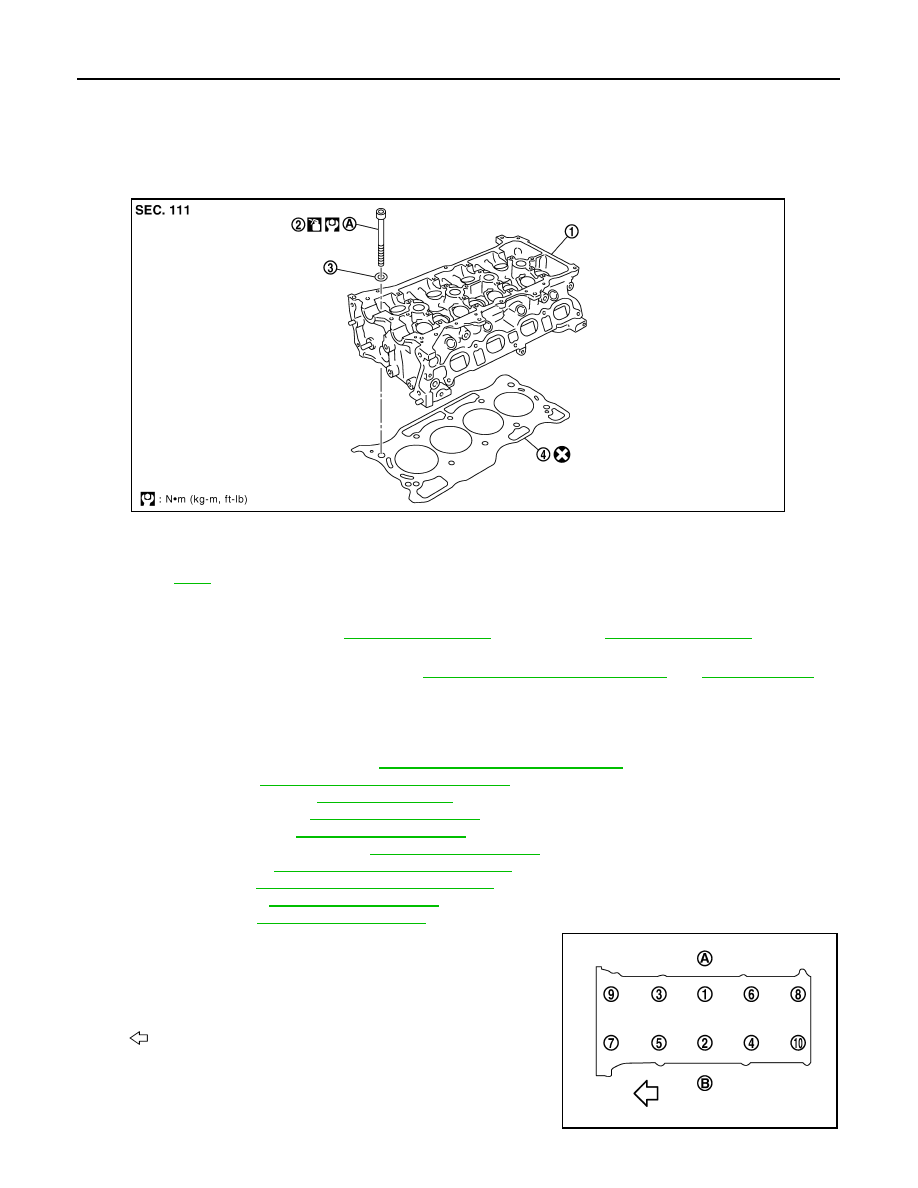
Removal and Installation
INFOID:0000000001381421
REMOVAL
1.
Release fuel pressure. Refer to
(EURO-OBD),
(WITHOUT
EURO-OBD).
2.
Drain engine coolant and engine oil. Refer to
CO-11, "Changing Engine Coolant"
.
CAUTION:
• Perform this step when the engine is cold.
• Never spill engine coolant and engine oil on drive belt.
3.
Remove the following components and related parts.
• Front fender protector (RH): Refer to
EXT-22, "Removal and Installation"
• Generator: Refer to
CHG-15, "Removal and Installation"
• Exhaust front tube: Refer to
.
• Exhaust manifold: Refer to
• Intake manifold: Refer to
• Fuel tube and fuel injector: Refer to
.
• Water outlet: Refer to
CO-24, "Removal and Installation"
• Drive belt: Refer to
EM-16, "Removal and Installation"
• Front cover: Refer to
• Camshaft: Refer to
.
4.
Remove cylinder head loosening bolts in reverse order as
shown with cylinder head wrench (commercial service tool).
1.
Cylinder head assembly
2.
Cylinder head bolt
3.
Washer
4.
Cylinder head gasket
A.
Refer to
PBIC3731E
A
: EXH side
B
: INT side
: Engine front
PBIC3732E