содержание .. 681 682 683 684 ..
Nissan Tiida C11. Manual - part 683
EM-84
< ON-VEHICLE REPAIR >
[HR16DE]
CYLINDER HEAD
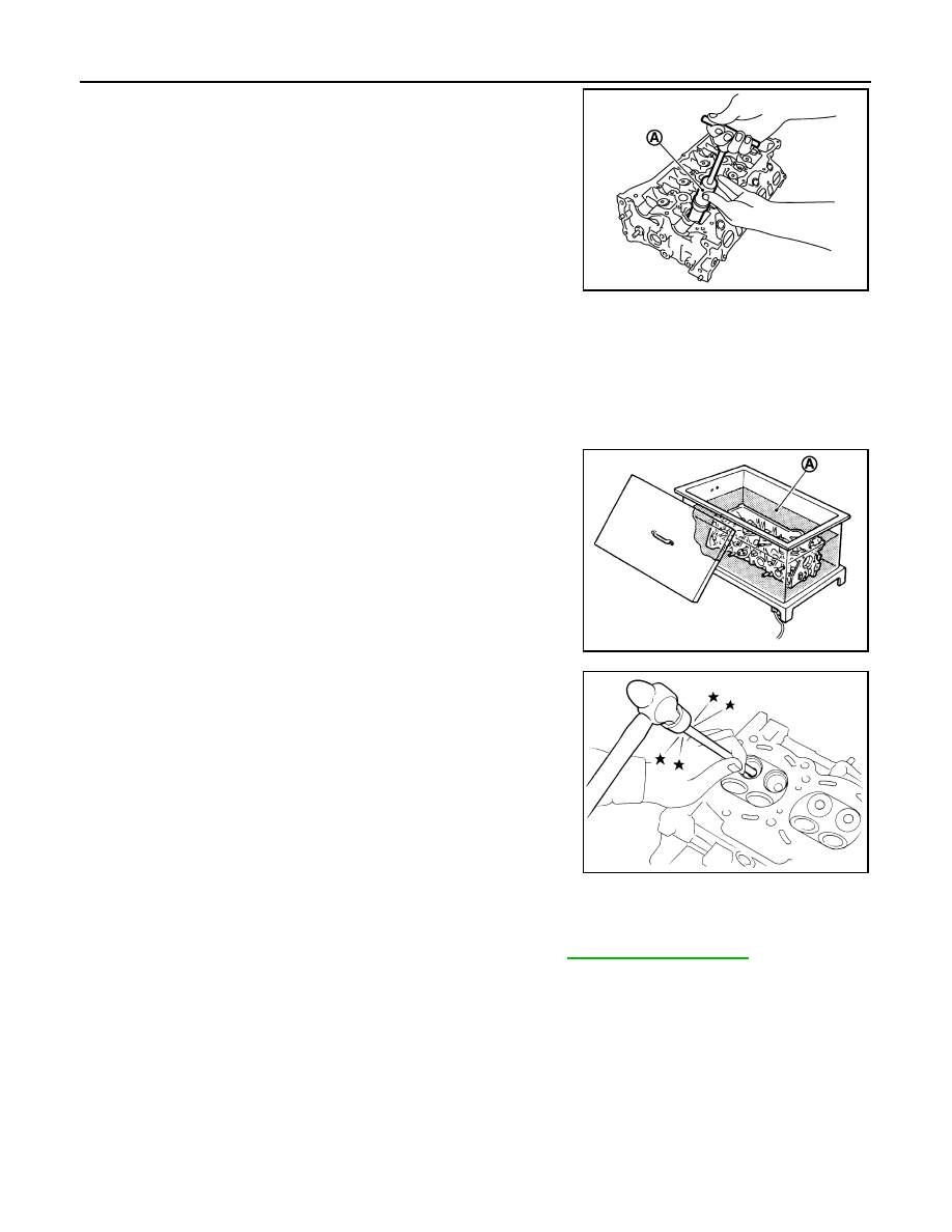
6.
Remove valve oil seal with the valve oil seal puller [SST:
KV10107902] (A).
7.
Remove valve spring seat.
8.
Remove valve seat, if valve seat must be replaced.
• Bore out old seat until it collapses. Boring should not continue beyond the bottom face of the seat
recess in cylinder head. Set the machine depth stop to ensure this.
CAUTION:
Never bore excessively to prevent cylinder head from scratching.
9.
Remove valve guide, if valve guide must be replaced.
a.
To remove valve guide, heat cylinder head to 110 to 130
°
C (230
to 266
°
F) by soaking in heated oil (A).
b.
Drive out valve guide with a press [under a 20 kN (2 ton, 2.2 US
ton, 2.0 lmp ton) pressure] or a hammer and the valve guide drift
(commercial service tool).
WARNING:
Cylinder head contains heat. Wear protective equipment to
avoid getting burned.
INSPECTION AFTER DISASSEMBLY
Valve Dimensions
• Check the dimensions of each valve. For the dimensions, refer to
• If dimensions are out of the standard, replace valve and check valve seat contact. Check “VALVE SEAT
CONTACT”.
Valve Guide Clearance
Valve Stem Diameter
PBIC3728E
JPBIA0184ZZ
SEM931C