содержание .. 640 641 642 643 ..
Nissan Tiida C11. Manual - part 642
EC-1218
< ECU DIAGNOSIS >
[K9K]
ECM
Terminal No.
Description
Condition
Value
(Approx.)
+
-–
Signal name
Input/
Output
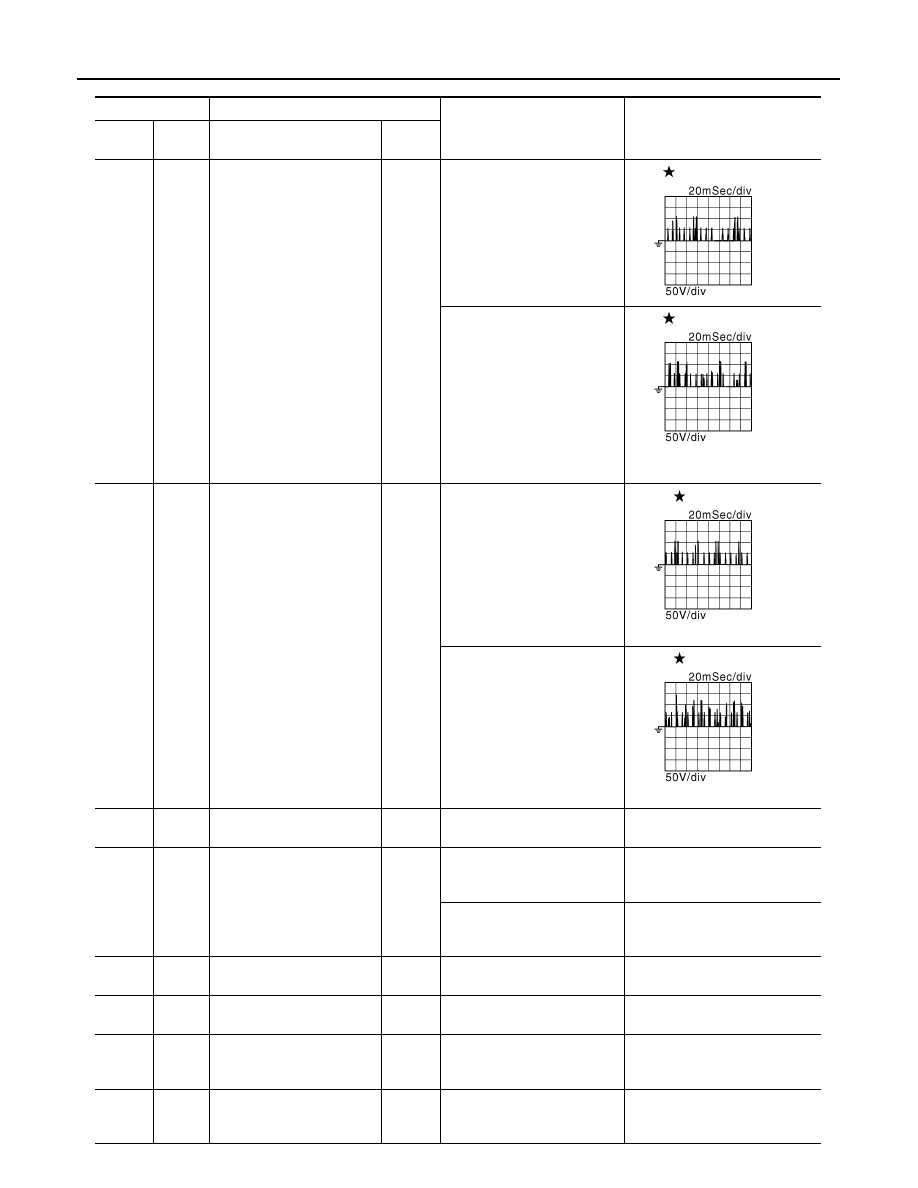
1
(SB)
128
(B)
Fuel injector No. 4
Input
[Engine is running]
• Warm-up condition
• Idle speed
NOTE:
The pulse cycle changes de-
pending on rpm at idle.
0- 9V
2
(SB)
Fuel injector No. 3
3
(SB)
Fuel injector No. 2
[Engine is running]
• Warm-up condition
• Engine speed: 2,000 rpm
0- 9V
4
(SB)
Fuel injector No. 1
5
(V)
128
(B)
Fuel injector power supply
No. 4
Output
[Engine is running]
• Warm-up condition
• Idle speed
NOTE:
The pulse cycle changes de-
pending on rpm at idle.
5 - 10V
6
(Y)
Fuel injector power supply
No. 3
7
(O)
Fuel injector power supply
No. 2
[Engine is running]
• Warm-up condition
• Engine speed: 2,000 rpm
5 - 10V
8
(L)
Fuel injector power supply
No. 1
15
(R)
—
Sensor ground
(Fuel rail pressure sensor)
—
—
—
19
(W)
15
(R)
Fuel rail pressure sensor
Input
[Engine is running]
• Warm-up condition
• Idle speed
Approximately 1.0V
[Engine is running]
• Warm-up condition
• Engine speed: 2,000 rpm
Approximately 1.5V
20
(G)
15
(R)
Sensor power supply
(Fuel rail pressure sensor)
—
[Ignition switch: ON]
Approximately 5.0V
28
(G)
30
(O)
Sensor power supply
(Mass air flow sensor)
—
[Ignition switch: ON]
Approximately 5.0V
29
(O)
—
Sensor ground
(Fuel pump temperature
sensor)
—
—
—
30
(O)
—
Sensor ground
(Mass air flow sensor/ Intake
air temperature sensor)
—
—
—
JMBIA0635GB
JMBIA0636GB
JMBIA0637GB
JMBIA0638GB