Nissan Tiida C11. Manual - part 641


  Главная      Nissan     Nissan Tiida C11 - Service Manual


поиск по сайту            


содержание   ..  639  640  641  642   ..


Nissan Tiida C11. Manual - part 641


EC-1214

< COMPONENT DIAGNOSIS >

[K9K]

STOP LAMP SWITCH

STOP LAMP SWITCH

Description

INFOID:0000000001162692

Brake switch signal is applied to the ECM through the stop lamp switch when the brake pedal is depressed.
This signal is used mainly to decrease the engine speed when the vehicle is driving.

Component Function Check

INFOID:0000000001162693

1.

CHECK BRAKE SWITCH FUNCTION 

1.

Turn ignition switch ON.

2.

Check the voltage between ECM harness connector and ground.

Is the inspection result normal?

YES

>> INSPECTION END.

NO

>> Go to 

EC-1214, "Diagnosis Procedure"

.

Diagnosis Procedure

INFOID:0000000001162694

1.

CHECK BRAKE SWITCH POWER SUPPLY CIRCUIT

1.

Turn ignition switch OFF.

2.

Disconnect stop lamp switch harness connector.

3.

Turn ignition switch ON.

4.

Check the voltage between stop lamp switch harness connector and ground.

Is the inspection result normal?

YES

>> GO TO 3.

NO

>> GO TO 2.

2.

DETECT MALFUNCTIONING PART

Check the following.
• Harness connectors M69, E7 (LHD models)
• Harness connectors M25, M201 (RHD models)
• 10A fuse (No. 7)
• Harness for open or short between fuse and stop lamp switch

>> Repair open circuit or short to ground or short to power in harness or connectors.

3.

CHECK BRAKE SWITCH INPUT SIGNAL CIRCUIT

1.

Turn ignition switch OFF.

2.

Disconnect ECM harness connector.

3.

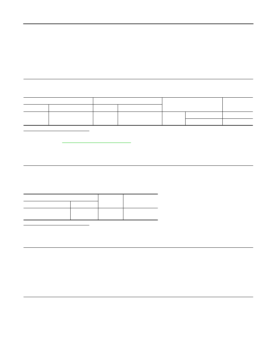
Check the continuity between stop lamp switch harness connector and ECM harness connector.

+

Condition

Voltage

Connector

Terminal

Connector

Terminal

E16

115

(Brake switch signal)

E16

128

Brake ped-
al

Fully released

0V

Slightly depressed

Battery voltage

Stop lamp switch

Ground

Voltage

Connector

Terminal

E13 (LHD models)

M203 (RHD models)

1

Ground

Battery voltage

STOP LAMP SWITCH

EC-1215

< COMPONENT DIAGNOSIS >

[K9K]

C

D

E

F

G

H

I

J

K

L

M

A

EC

N

P

O

4.

Also check harness for short to ground and short to power. 

Is the inspection result normal?

YES

>> GO TO 5.

NO

>> GO TO 4.

4.

DETECT MALFUNCTIONING PART

Check the following.
• Harness connectors M25, M201 (RHD models)
• Harness connectors M69, E7 (RHD models)
• Harness for open or short between fuse and stop lamp switch

>> Repair open circuit or short to ground or short to power in harness or connectors.

5.

CHECK STOP LAMP SWITCH 

Refer to 

EC-1215, "Component Inspection"

.

Is the inspection result normal?

YES

>> GO TO 6.

NO

>> Replace stop lamp switch.

6.

CHECK INTERMITTENT INCIDENT

Refer to 

GI-55, "Intermittent Incident"

.

>> INSPECTION END

Component Inspection

INFOID:0000000001162695

1.

CHECK STOP LAMP SWITCH-I

1.

Turn ignition switch OFF.

2.

Disconnect stop lamp switch harness connector.

3.

Check the continuity between stop lamp switch terminals under the following conditions.

Is the inspection result normal?

YES

>> INSPECTION END

NO

>> GO TO 2.

2.

CHECK STOP LAMP SWITCH-II

1.

Adjust stop lamp switch installation. Refer to 

BR-6, "Inspection and Adjustment"

.

2.

Check the continuity between stop lamp switch terminals under the following conditions.

Is the inspection result normal?

YES

>> INSPECTION END

NO

>> Replace stop lamp switch.

Stop lamp switch

ECM

Continuity

Connector

Terminal

Connector

Terminal

E13 (LHD models)

M203 (RHD models)

2

E16

115

Existed

Terminals

Condition

Continuity

1 and 2
(Stop lamp switch)

Brake pedal

Fully released

Not existed

Slightly depressed

Existed

Terminals

Condition

Continuity

1 and 2
(Stop lamp switch)

Brake pedal

Fully released

Not existed

Slightly depressed

Existed

EC-1216

< ECU DIAGNOSIS >

[K9K]

ECM

ECU DIAGNOSIS

ECM

Reference Value

INFOID:0000000001538652

VALUE ON THE DIAGNOSIS TOOL

Remarks:

 Specification data are reference values.

 Specification data are output/input values which are detected or supplied by the ECM at the connector.

* Specification data may not be directly related to their components signals/values/operations.

MONITOR ITEM

CONDITION

SPECIFICATION

ENGINE SPEED

• Run engine and compare CONSULT-III value with the tachometer 

indication.

Almost the same speed as the tachom-
eter indication

ACCEL/PDL POS

• Ignition switch: ON

(Engine stopped)

Accelerator pedal: Fully released

0%

WATER TEMP

• Engine: After warming up

More than 70

°

C (158

°

F)

FUEL TEMP

• Engine: After warming up

More than 40

°

C (104

°

F)

BATTERY VOLTAGE

• Ignition switch: ON (Engine stopped)

11 - 14V

ATMOS PRESS

• Ignition switch: ON

Altitude
Approx. 0m: Approx. 100.62 kPa 

(1.0062 bar, 1.026 kg/cm

2

, 14.59 psi)

Approx. 1,000 m: Approx. 88.95 kPa 

(0.8895 bar, 0.907 kg/cm

2

, 12.90 psi)

Approx. 1,500 m: Approx. 83.16 kPa 

(0.8316 bar, 0.848 kg/cm

2

, 12.06 psi)

Approx. 2,000 m: Approx. 78.36 kPa 

(0.7836 bar, 0.799 kg/cm

2

, 11.36 psi)

INLET PRESS

• Engine: After warming up
• Air conditioner switch: OFF
• Shift lever: Neutral position
• No  load

Idle

Approximately 980 mbar

2,000 rpm

Approximately 1,010 mbar

AIR FLOW

• Engine: After warming up 
• Air conditioner switch: OFF
• Shift lever: Neutral position
• No  load

Idle

Approximately 200 mg/cp

2,000 rpm

Approximately 270 mg/cp

VEHICLE SPEED

• Turn drive wheels and compare CONSULT-III value with the 

speedometer indication

Almost the same speed as the speed-
ometer indication

RAIL PRESSURE

• Engine: After warming up
• Air conditioner switch: OFF
• Shift lever: Neutral position
• No  load

Idle

Approximately 230 bar

2,000 rpm

Approximately 450 bar

RAIL PRES SET

• Engine: After warming up
• Air conditioner switch: OFF
• Shift lever: Neutral position
• No  load

Idle

Approximately 230 bar

2,000 rpm

Approximately 450 bar

FUEL FLOW

• Engine: After warming up
• Air conditioner switch: OFF
• Shift lever: Neutral position
• No  load

Idle

Approximately 4.9 mg/cp

2,000 rpm

Approximately 3.5 mg/cp

EGR PO RECOPY

• Engine: After warming up
• Air conditioner switch: OFF
• Shift lever: Neutral position
• No  load

Idle

Approximately -50 %

EGR/V OPEN REF

• Engine: After warming up
• Air conditioner switch: OFF
• Shift lever: Neutral position
• No  load

Idle

Approximately -50 %

ECM

EC-1217

< ECU DIAGNOSIS >

[K9K]

C

D

E

F

G

H

I

J

K

L

M

A

EC

N

P

O

TERMINAL LAYOUT

PHYSICAL VALUES

NOTE:
• ECM is located in engine room, between air filter and battery.
• When disconnecting ECM harness connector (1), loosen (B) it with

levers as far as they will go as shown in the figure.

• Pulse signal is measured by CONSULT-III.

RFRGERNT PRSS

• Engine: After warming up
• Air conditioner switch: OFF
• Shift lever: Neutral position
• No  load

Idle

Approximately 5.7 bar

PWR ABSOB A/C

• Engine: After warming up
• Air conditioner switch: OFF
• Shift lever: Neutral position
• No  load

Idle

Approximately 0 W

PL PTNMR T1 V

• Ignition switch: ON

(Engine stopped)

Accelerator pedal: Fully released

Approximately 15 %

PL PTNMR T2 V

• Ignition switch: ON

(Engine stopped)

Accelerator pedal: Fully released

Approximately 6 %

EGR POS SE VO

• Engine: After warming up
• Air conditioner switch: OFF
• Shift lever: Neutral position
• No  load

Idle

Approximately 3.56 V

RAIL PRES S V

• Engine: After warming up
• Air conditioner switch: OFF
• Shift lever: Neutral position
• No  load

Idle

Approximately 1 V

2,000 rpm

Approximately 1.5 V

MONITOR ITEM

CONDITION

SPECIFICATION

JMBIA0417ZZ

2

:  ECM

A

:  Fasten

MBIB1518E


содержание   ..  639  640  641  642   ..