Nissan Tiida C11. Manual - part 597


  Главная      Nissan     Nissan Tiida C11 - Service Manual


поиск по сайту            


содержание   ..  595  596  597  598   ..


Nissan Tiida C11. Manual - part 597


EC-1038

< SERVICE DATA AND SPECIFICATIONS (SDS) 

[MR18DE]

SERVICE DATA AND SPECIFICATIONS (SDS)

SERVICE DATA AND SPECIFICATIONS (SDS)

SERVICE DATA AND SPECIFICATIONS (SDS)

Idle Speed

INFOID:0000000001162007

*: Under the following conditions

• A/C switch: OFF

• Electric load: OFF (Lights, heater fan & rear window defogger)

• Steering wheel: Kept in straight-ahead position

Ignition Timing

INFOID:0000000001162008

*: Under the following conditions

• A/C switch: OFF

• Electric load: OFF (Lights, heater fan & rear window defogger)

• Steering wheel: Kept in straight-ahead position

Calculated Load Value

INFOID:0000000001162009

Mass Air Flow Sensor

INFOID:0000000001162010

*: Engine is warmed up to normal operating temperature and running under no load.
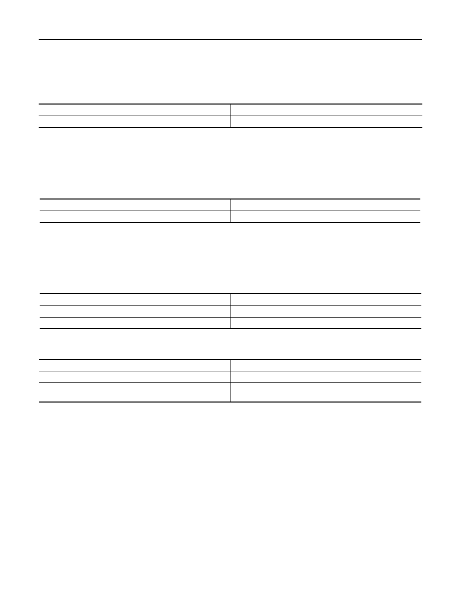
Condition

Specification

No load* (in Neutral position)

700 

±

 50 rpm

Condition

Specification

No load* (in Neutral position)

15 

±

 5

°

 BTDC

Condition

Specification (Using CONSULT-III or GST)

At idle

10 – 35 %

At 2,500 rpm

10 – 35 %

Supply voltage

Battery voltage (11 – 14 V)

Output voltage at idle

0.8 – 1.1V*

Mass air flow (Using CONSULT-III or GST)

1.0 – 4.0 g·m/sec at idle*

2.0 – 10.0 g·m/sec at 2,500 rpm*

DIAGNOSIS AND REPAIR WORKFLOW

EC-1039

< BASIC INSPECTION >

[K9K]

C

D

E

F

G

H

I

J

K

L

M

A

EC

N

P

O

BASIC INSPECTION

DIAGNOSIS AND REPAIR WORKFLOW

Work Flow

INFOID:0000000001162512

OVERALL SEQUENCE

Diagnostics Malfunctions

JMBIA0634GB

EC-1040

< BASIC INSPECTION >

[K9K]

DIAGNOSIS AND REPAIR WORKFLOW

• Malfunctions are declared as either present or stored (depending on whether they appeared in a certain con-

text and have disappeared since, or whether they remain present but have not been diagnosed within the
current context).

• The present or stored status of malfunctions should be taken into consideration when the diagnostic tool is

used following the + after ignition supply being switched on (without acting on the system components).

• For a present malfunction, apply the procedure described in the Interpretation of malfunction section.
• For a stored malfunction, note the malfunctions displayed and apply the instructions in the Notes section.
• If the malfunction is confirmed when the instructions in the Notes section are applied, the malfunction is

present. Deal with the malfunction

• If the malfunction is not confirmed, check:
- the electrical lines which correspond to the malfunction,
- the connectors for these lines (for oxidation, bent pins, etc),
- the condition of the wires (insulation has melted or been cut, abrasions),
- the resistance of the component detected as malfunction.

Conformity Check

• The aim of the conformity check is to check data that does not produce a malfunction on the diagnostic tool

because the data is inconsistent. Therefore, this phase is used to:

- carry out malfunction finding on malfunctions that do not have a malfunction display, and which may corre-

spond to a customer complaint.

- check that the system is operating correctly and that there is no risk of a malfunction recurring after repairs.
• This section gives the malfunction finding procedures for statuses and parameters and the conditions for

checking them.

• If a status is not behaving normally or a parameter is outside the permitted tolerance values, consult the cor-

responding malfunction finding page.

Customer Complaints - Malfunction finding chart

If the test with the diagnostic tool is OK but the customer complaint is still present, the malfunction should be
processed by customer complaint.
NOTE:
A synopsis of the general procedure to follow is provided on the preceding page in the form of a flow
chart.

Malfunction Finding Procedure (Wiring Check)

Diagnostics malfunctions
Removing the connectors and/or handling the wirings may temporarily remove the origin of a DTC. The mea-
surements of the electrical voltages, resistance and insulation are generally correct, especially when the DTC
is not present at the time of the analysis (stored DTC).
Visual Check
Look for impacts under the bonnet and in the passenger compartment.
Perform a careful check of the protections, insulation and correct running of wirings.
Look for traces of oxidation.
Tactile Check
While manipulating the wirings, use the diagnostic tool to detect a change in DTC status from “stored” to
“present”.
Ensure that the connectors are correctly engaged.
Apply light stresses to the connectors.
Gently manipulate the wiring harness.
If a change of status occurs, try to isolate the origin of the incident.
Inspection of each component
Disconnect the connectors and check the appearance of the clips and blades and their crimping (no crimping
on the insulating part).
Check that the clips and blades are properly engaged in the receptacles.
Ensure that there is no rebounding of clips or blades at the time of connection.
Check the contact pressure of the clips using a suitable model blade.
Resistance Control
Test the continuity of the lines in their entirety, then section by section.
Try to create a short-circuit to earth, on the + 12 V or with another wire.
If a DTC is detected, repair or replace the wiring.

REMINDERS

Trouble Diagnosis:

DIAGNOSIS AND REPAIR WORKFLOW

EC-1041

< BASIC INSPECTION >

[K9K]

C

D

E

F

G

H

I

J

K

L

M

A

EC

N

P

O

There are present DTCs and stored DTCs (which appeared in a certain context and have since disappeared
or which are still present but have not had trouble diagnosis performed on them in the current context).
The “present” or “stored” status of DTCs must be considered when activating the diagnostic tool after power is
supplied to the ECM (without activating the system components).
Deal with present DTCs according to the procedure specified in the corresponding DTC trouble diagnosis.
For stored DTCs, note the DTCs displayed and follow the instructions in the Notes section.
If the DTC is confirmed when the instructions in the Notes section are applied, the malfunction is present. Deal
with the DTC.

If the DTC is not confirmed, check:

• Electrical lines which correspond to the malfunction
• Connectors for these lines (for oxidation, bent pins, etc.)
• Resistance of the malfunction component
• Condition of the wires (melted or cut insulation, wear)

Conformity Check

The conformity check is designed to check the states and data monitor items which do not display any DTCs
on the diagnostic tool when inconsistent. This phase therefore allows:
• Diagnoses malfunctions that do not have a DTC display, and which may correspond to a customer com-

plaint.

• Checks that the system is operating correctly and that there is no risk of a DTC reappearing after repairs.
This section gives the trouble diagnosis procedures for states and parameters and the conditions for checking
them.
If a state is not operating normally or a data monitor value is outside permitted tolerance values, you should
consult the corresponding trouble diagnosis page.

Customer Complaints - Trouble Diagnosis

If the test with the CONSULT-III is OK, but the customer complaint still present, the malfunction should be
treated by customer complaints.

SAFETY ADVICE

• The safety instructions must be followed at all times when working on components, to avoid damage or

injury:

- make sure that the battery is properly charged to avoid damaging the computers with a low load,
- use the appropriate tools,
- do not touch the xenon bulbs.

Diagnostic Work Sheet

INFOID:0000000001162513

DESCRIPTION

There are many operating conditions that lead to the malfunction of
engine components. A good grasp of such conditions can make trou-
bleshooting faster and more accurate.
In general, each customer feels differently about a incident. It is
important to fully understand the symptoms or conditions for a cus-
tomer complaint.
Utilize a diagnostic worksheet like the one on the next page in order
to organize all the information for troubleshooting.
Some conditions may cause the MI to come on steady or blink and
DTC to be detected. Examples:
• Vehicle ran out of fuel, which caused the engine to misfire.
• Fuel filler cap was left off or incorrectly screwed on, allowing fuel to

evaporate into the atmosphere.

A synopsis of the general procedure to follow is pro-
vided on the previous page in the form of a flow 
chart.

SEF907L


содержание   ..  595  596  597  598   ..