Nissan Tiida C11. Manual - part 596


  Главная      Nissan     Nissan Tiida C11 - Service Manual


поиск по сайту            


содержание   ..  594  595  596  597   ..


Nissan Tiida C11. Manual - part 596


EC-1034

< PREPARATION >

[MR18DE]

PREPARATION

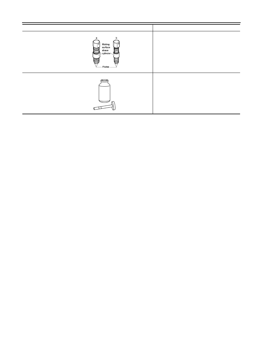
Oxygen sensor thread 
cleaner

Reconditioning the exhaust system threads before 
installing a new oxygen sensor. Use with anti-
seize lubricant shown below.
a: 18 mm diameter with pitch 1.5 mm for Zirco-
nia Oxygen Sensor
b: 12 mm diameter with pitch 1.25 mm for Tita-
nia Oxygen Sensor

Anti-seize lubricant 

i.e.: (Permatex

TM


133AR or equivalent 
meeting MIL specifica-
tion MIL-A-907)

Lubricating oxygen sensor thread cleaning tool 
when reconditioning exhaust system threads.

Tool name

Description

AEM488

S-NT779

FUEL PRESSURE

EC-1035

< ON-VEHICLE REPAIR >

[MR18DE]

C

D

E

F

G

H

I

J

K

L

M

A

EC

N

P

O

ON-VEHICLE REPAIR

FUEL PRESSURE

Inspection

INFOID:0000000001162005

FUEL PRESSURE RELEASE

 With CONSULT-III

1.

Turn ignition switch ON.

2.

Perform “FUEL PRESSURE RELEASE” in “WORK SUPPORT” mode with CONSULT-III.

3.

Start engine.

4.

After engine stalls, crank it two or three times to release all fuel pressure.

5.

Turn ignition switch OFF.

 With CONSULT-III

1.

Remove fuel pump fuse located in IPDM E/R.

2.

Start engine.

3.

After engine stalls, crank it two or three times to release all fuel pressure.

4.

Turn ignition switch OFF.

5.

Reinstall fuel pump fuse after servicing fuel system.

FUEL PRESSURE CHECK

CAUTION:

• Before disconnecting fuel line, release fuel pressure from fuel line to eliminate danger.
• The fuel hose connection method used when taking fuel pressure check must not be used for other

purposes.

• Be careful not to scratch or put debris around connection area when servicing, so that the quick

connector maintains sealability with O-rings inside.

• Do not perform fuel pressure check with electrical systems operating (i.e. lights, rear defogger, A/C,

etc.) Fuel pressure gauge may indicate false readings due to varying engine load and changes in
manifold vacuum.

NOTE:
Prepare pans or saucers under the disconnected fuel line because the fuel may spill out. The fuel pres-
sure cannot be completely released because C11 models do not have fuel return system.

1.

Release fuel pressure to zero.

2.

Prepare fuel hose for fuel pressure check B and fuel tube
adapter (KV10118400) D, then connect fuel pressure gauge A.

: To quick connector

: To fuel tube (engine side)

• C: Clamp
•  Use suitable fuel hose for fuel pressure check (genuine NIS-

SAN fuel hose without quick connector).

• To avoid unnecessary force or tension to hose, use moder-

ately long fuel hose for fuel pressure check.

• Do not use the fuel hose for checking fuel pressure with dam-

age or cracks on it.

• Use Pressure Gauge to check fuel pressure.

3.

Remove fuel hose.
• Do not twist or kink fuel hose because it is plastic hose.

PBIB2982E

EC-1036

< ON-VEHICLE REPAIR >

[MR18DE]

FUEL PRESSURE

4.

Connect fuel hose for fuel pressure check (1) to fuel tube
(engine side) with clamp (2) as shown in the figure.
• No.2 spool (5)
• Wipe off oil or dirt from hose insertion part using cloth moist-

ened with gasoline.

• Apply proper amount of gasoline between top of the fuel tube

(3) and No.1 spool (4).

• Insert fuel hose for fuel pressure check until it touches the

No.1 spool on fuel tube.

• Use NISSAN genuine hose clamp (part number: 16439 N4710

or 16439 40U00).

• When reconnecting fuel line, always use new clamps.
• Use a torque driver to tighten clamps.
• Install hose clamp to the position within 1 - 2 mm (0.04 - 0.08 in).

• Make sure that clamp screw does not contact adjacent parts.

5.

Connect fuel tube adapter to quick connector.
• A: Fuel pressure gauge
• B: Fuel hose for fuel pressure check

6.

After connecting fuel hose for fuel pressure check, pull the hose
with a force of approximately 98 N (10 kg, 22 lb) to confirm fuel
tube does not come off.

7.

Turn ignition switch ON and check for fuel leakage.

8.

Start engine and check for fuel leakage.

9.

Read the indication of fuel pressure gauge.
• Do not perform fuel pressure check with system operating.

Fuel pressure gauge may indicate false readings.

• During fuel pressure check, confirm for fuel leakage from fuel connection every 3 minutes.

10. If result is unsatisfactory, go to next step.

11. Check the following.

• Fuel hoses and fuel tubes for clogging
• Fuel filter for clogging
• Fuel pump 
• Fuel pressure regulator for clogging
If OK, replace fuel pressure regulator.
If NG, repair or replace.

Tightening torque:

1 - 1.5 N·m (0.1 - 0.15 kg-m, 9 - 13 in-lb)

At idling:

Approximately 350 kPa (3.5 bar, 3.57 kg/cm

2

, 51 psi)

PBIB2983E

PBIB2984E

EVAPORATIVE EMISSION SYSTEM

EC-1037

< ON-VEHICLE REPAIR >

[MR18DE]

C

D

E

F

G

H

I

J

K

L

M

A

EC

N

P

O

EVAPORATIVE EMISSION SYSTEM

Inspection

INFOID:0000000001162006

1.

Visually inspect EVAP vapor lines for improper attachment and for cracks, damage, loose connections,
chafing and deterioration.

2.

Check EVAP canister as follows:

a.

Block port (B). Orally blow air through port (A).
Check that air flows freely through port (C).

b.

Block port (A). Orally blow air through port (B).
Check that air flows freely through port (C).

3.

Visually inspect the fuel check valve for cracks, damage, loose connections chafing and deterioration. 

4.

Check fuel check valve as follows:

a.

Blow air through connector on the fuel tank side. A considerable
resistance should be felt and a portion of air flow should be
directed toward the EVAP canister side.

b.

Blow air through connector on EVAP canister side. Air flow
should be smoothly directed toward fuel tank side.

c.

If fuel check valve is suspected or not properly functioning in
step 1 and 2 above, replace it.

5.

Inspect fuel tank filler cap vacuum relief valve for clogging, stick-
ing, etc.

a.

Wipe clean valve housing.

b.

Check valve opening pressure and vacuum.

c.

If out of specification, replace fuel filler cap as an assembly.

PBIB0663E

SEF552Y

SEF989X

Pressure:

15.3 - 20.0 kPa (0.153 - 0.200 bar, 0.156 - 0.204 kg/

cm

2

, 2.22 - 2.90 psi)

Vacuum:

–6.0 to –3.4 kPa (–0.06 bar to –-0.034bar, –0.061 to –

0.035 kg/cm

2

, –0.87 to –0.49 psi)

SEF943S


содержание   ..  594  595  596  597   ..