содержание .. 1340 1341 1342 1343 ..
Nissan Tiida C11. Manual - part 1342
A/T SHIFT LOCK SYSTEM
TM-419
< COMPONENT DIAGNOSIS >
[TYPE 2 (4AT: RE4F03B)]
C
E
F
G
H
I
J
K
L
M
A
B
TM
N
O
P
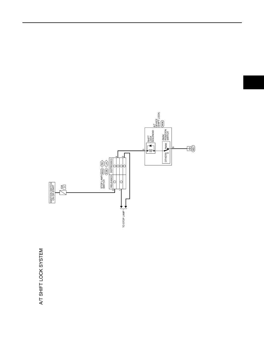
A/T SHIFT LOCK SYSTEM
Wiring Diagram - A/T Shift Lock System -
INFOID:0000000001731057
Terminals And Reference Values
INFOID:0000000001731059
SHIFT LOCK CONTROL UNIT INSPECTION TABLE
ALDWA0058GB