содержание .. 1309 1310 1311 1312 ..
Nissan Tiida C11. Manual - part 1311
REPAIR FOR COMPONENT PARTS
TM-295
< DISASSEMBLY AND ASSEMBLY >
[TYPE 1 (4AT: RE4F03B)]
C
E
F
G
H
I
J
K
L
M
A
B
TM
N
O
P
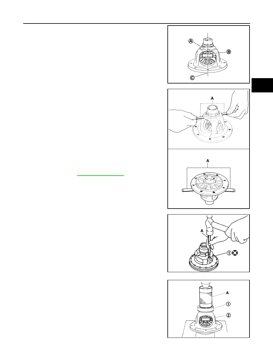
a.
Place differential case in the upright position so that the side
gear to be measured is at the top.
(A): Location for inserting feeler gauge
(B): Side gear tooth
(C): The center line of differential case
b.
In order to maximize the back clearance, rotate side gears so
that a tooth on side gears at the top and bottom will align at the
same position as shown.
c.
Adjust the back clearance of side gear according to the following
procedures.
i.
Insert feeler gauges (A) of the same thickness to the back of
side gear from both sides, preventing side gear from falling, to
measure the clearance.
• Measure clearance 3 times by rotating side gears and take the
average.
CAUTION:
In all 3 measurements, maximize the clearance by aligning
teeth on side gears at the top and bottom at the same posi-
tion.
ii.
Select side gear thrust washer so that the clearance will fall
within the standard.
iii.
Turn differential case upside down, and measure the back clear-
ance of the other side gear in the same manner.
NOTE:
Adjust the clearance to approx. 0.1 mm (0.004 in) for used differ-
ential [driven approx. 3,000 km (1864 mile) or more].
3.
Install lock pin (1) to pinion mate shaft using Tool (A).
CAUTION:
Make sure that lock pin (1) flush with differential case.
4.
Set Tool (A) on differential side bearing (RH side) (1), and press
differential side bearing (RH side) (1) to differential case (2).
CAUTION:
Set Tool (A) on differential side bearing inner race.
SCIA7064E
Differential side gear clearance:
.
SCIA7061E
Tool number:
KV32101000
SCIA7228E
Tool number:
ST33200000
SCIA7062E