содержание .. 1308 1309 1310 1311 ..
Nissan Tiida C11. Manual - part 1310
REPAIR FOR COMPONENT PARTS
TM-291
< DISASSEMBLY AND ASSEMBLY >
[TYPE 1 (4AT: RE4F03B)]
C
E
F
G
H
I
J
K
L
M
A
B
TM
N
O
P
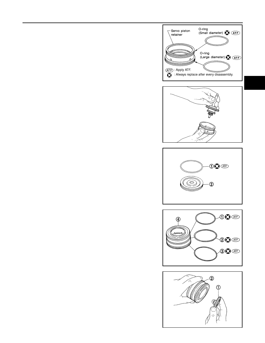
4.
Install O-rings to servo piston retainer
5.
Install band servo piston assembly to servo piston retainer by
pushing it inward.
6.
Install D-ring (1) to OD servo piston (2).
7.
Install O-rings (1), (2) and (3) to OD servo piston retainer (4).
(1): O-ring (small diameter)
(2): O-ring (medium diameter)
(3): O-ring (large diameter)
8.
Install OD servo piston (1) to OD servo piston retainer (2) as
shown.
SCIA3671E
SAT303D
SCIA7053E
SCIA6492J
SCIA7057E