Nissan Tiida C11. Manual - part 1289


  Главная      Nissan     Nissan Tiida C11 - Service Manual


поиск по сайту            


содержание   ..  1287  1288  1289  1290   ..


Nissan Tiida C11. Manual - part 1289


KEY INTERLOCK CABLE

TM-207

< ON-VEHICLE REPAIR >

[TYPE 1 (4AT: RE4F03B)]

C

E

F

G

H

I

J

K

L

M

A

B

TM

N

O

P

7.

Remove steering column cover (upper and lower) and instru-
ment lower finisher. Refer to 

IP-11, "Removal and Installation"

.

8.

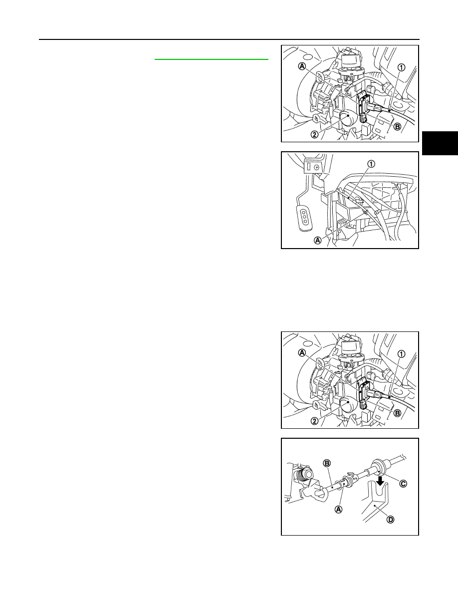
Pull out the lock plate (A) from the holder (B).

9.

Remove the key interlock cable (1) from the key cylinder (2).

10. Remove the clip (A), and then remove the key interlock cable

(1).

INSTALLATION

CAUTION:

• Install key interlock cable in such a way that it will not be damaged by sharp bends, twists or interfer-

ence with adjacent parts.

• After installing key interlock cable to control device assembly, make sure that casing cap and

bracket are firmly secured in their positions.

1.

Place the selector lever in the “P” position.

2.

Turn ignition switch to “ACC” or “ON” position.

3.

Set the key interlock cable (1) to the key cylinder (2).

4.

Install the lock plate (A) to the holder (B).

5.

Turn ignition switch to “LOCK” position.

6.

Temporarily install the adjust holder (A) to the key interlock rod
(B).

7.

Install the casing cap (C) to the cable bracket (D) on the control
device assembly.

CAUTION:

• Do not bend or twist key interlock cable excessively when

installing.

• After installing key interlock cable to cable bracket (D) on

control device assembly, make sure casing cap (C) is
firmly secured in cable bracket (D) on control device
assembly.

• If casing cap (C) is loose [less than 39.2 N (4.0 kg, 8.8 lb)

removing force], replace key interlock cable.

SCIA6976E

SCIA6973E

SCIA6976E

SCIA6188E

TM-208

< ON-VEHICLE REPAIR >

[TYPE 1 (4AT: RE4F03B)]

KEY INTERLOCK CABLE

8.

Slide the slider (A) toward the key interlock rod (D) while press-
ing the pull lock (B) down to securely connect the adjust holder
(C) with the key interlock rod (D).

CAUTION:

• Do not press tabs when holding slider (A).
• Do not apply any side to side force to key interlock rod (D)

when sliding slider (A).

9.

Secure the key interlock cable (1) with the clip (A).

10. Install steering column cover (upper and lower) and instrument

lower finisher. Refer to 

IP-11, "Removal and Installation"

.

11. Install the center console assembly. Refer to 

IP-11, "Removal

and Installation"

.

12. Install the selector lever knob. Refer to 

TM-203, "Selector Lever

Knob Removal and Installation"

.

13. Check shift lock system. Refer to 

TM-31, "System Description"

.

SCIA6978E

SCIA6973E

AIR BREATHER HOSE

TM-209

< ON-VEHICLE REPAIR >

[TYPE 1 (4AT: RE4F03B)]

C

E

F

G

H

I

J

K

L

M

A

B

TM

N

O

P

AIR BREATHER HOSE

Removal and Installation

INFOID:0000000001731381

COMPONENTS

REMOVAL

1.

Remove air duct (inlet), air duct and air cleaner case. Refer to 

EM-27, "Removal and Installation"

.

2.

Remove air breather hose.

INSTALLATION

Installation is in the reverse order of removal.

CAUTION:

Make sure air breather hose is not collapsed or blocked due to folding or bending when installed.
NOTE:
• Install the air breather hose (1) to the air breather tube (2) so that

the paint mark (A) faces upward. Also make sure the air breather
hose end laps with air breather tube 17 mm (0.67 in) or more.

• When installing air breather hose (1) to air duct and air cleaner

case, make sure to fully insert the hose clips.

1.

Air cleaner case

2.

Air duct

3.

Air breather hose

4.

Clip

5.

Air breather tube

6.

A/T

WCIA0642E

WCIA0641E

TM-210

< REMOVAL AND INSTALLATION >

[TYPE 1 (4AT: RE4F03B)]

TRANSAXLE ASSEMBLY

REMOVAL AND INSTALLATION

TRANSAXLE ASSEMBLY

Exploded View

INFOID:0000000001731386

Removal and Installation

INFOID:0000000001731383

REMOVAL 

1.

Remove the engine and transaxle as an assembly. Refer to 

EM-89, "Removal and Installation"

.

1.

Rear torque rod

2.

Rear engine mounting bracket

3.

A/T fluid charging pipe

4.

A/T fluid level gauge

5.

O-ring

6.

Fluid cooler tube

7.

Copper washer

8.

Bracket

9.

Fluid cooler tube

10. A/T assembly

11.

Rear gusset

12. Engine mounting bracket (LH)

13. Bracket

14. Washer

:  Refer to installation.

SCIA8261E


содержание   ..  1287  1288  1289  1290   ..