содержание .. 1288 1289 1290 1291 ..
Nissan Tiida C11. Manual - part 1290
TRANSAXLE ASSEMBLY
TM-211
< REMOVAL AND INSTALLATION >
[TYPE 1 (4AT: RE4F03B)]
C
E
F
G
H
I
J
K
L
M
A
B
TM
N
O
P
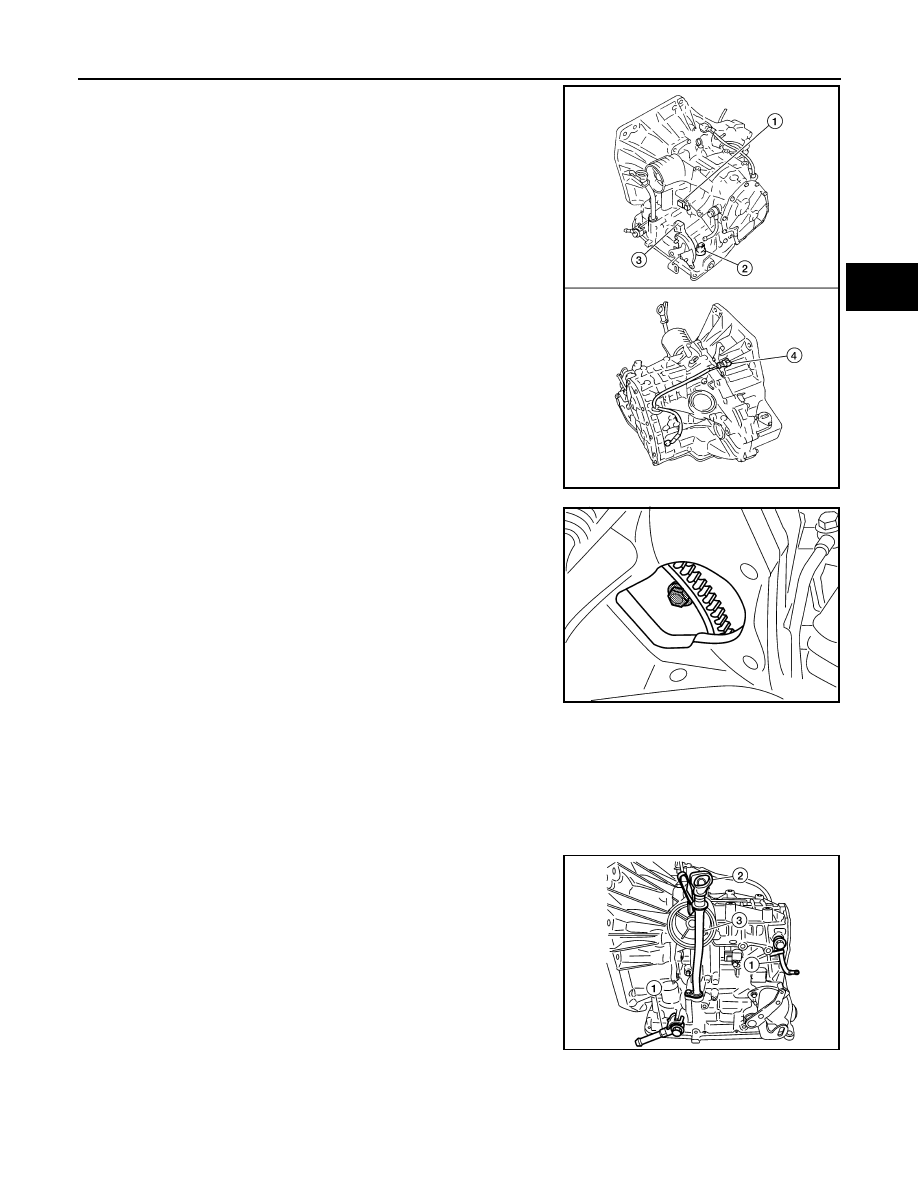
2.
Disconnect the following connectors and remove the wire har-
ness.
• Turbine revolution sensor (power train revolution sensor) har-
ness connector (1)
• Terminal cord assembly harness connector (2)
• PNP switch connector (3)
• Revolution sensor harness connector (4)
3.
Remove the four drive plate to torque converter bolts.
NOTE:
Rotate the crankshaft clockwise as viewed from front of engine
for access to drive plate to torque converter bolts.
4.
Put matching marks on the drive plate and torque converter.
CAUTION:
For matching marks, use paint. Never damage the drive plate or torque converter.
5.
Remove the transaxle to engine and engine to transaxle bolts.
6.
Separate the transaxle from the engine.
CAUTION:
Secure torque converter to prevent it from dropping.
7.
If necessary, remove the following from the transaxle:
• Fluid cooler tubes (1) and copper washers
• A/T fluid level gauge (2) and charging pipe (3)
• PNP switch
• Air breather hose
• Engine mounting bracket (LH)
• Any necessary brackets
INSPECTION
WCIA0647E
WCIA0616E
WCIA0648E