Nissan Tiida C11. Manual - part 1285


  Главная      Nissan     Nissan Tiida C11 - Service Manual


поиск по сайту            


содержание   ..  1283  1284  1285  1286   ..


Nissan Tiida C11. Manual - part 1285


CONTROL SYSTEM

TM-191

< ON-VEHICLE REPAIR >

[TYPE 1 (4AT: RE4F03B)]

C

E

F

G

H

I

J

K

L

M

A

B

TM

N

O

P

CONTROL SYSTEM

Control Valve Assembly and Accumulators

INFOID:0000000001733158
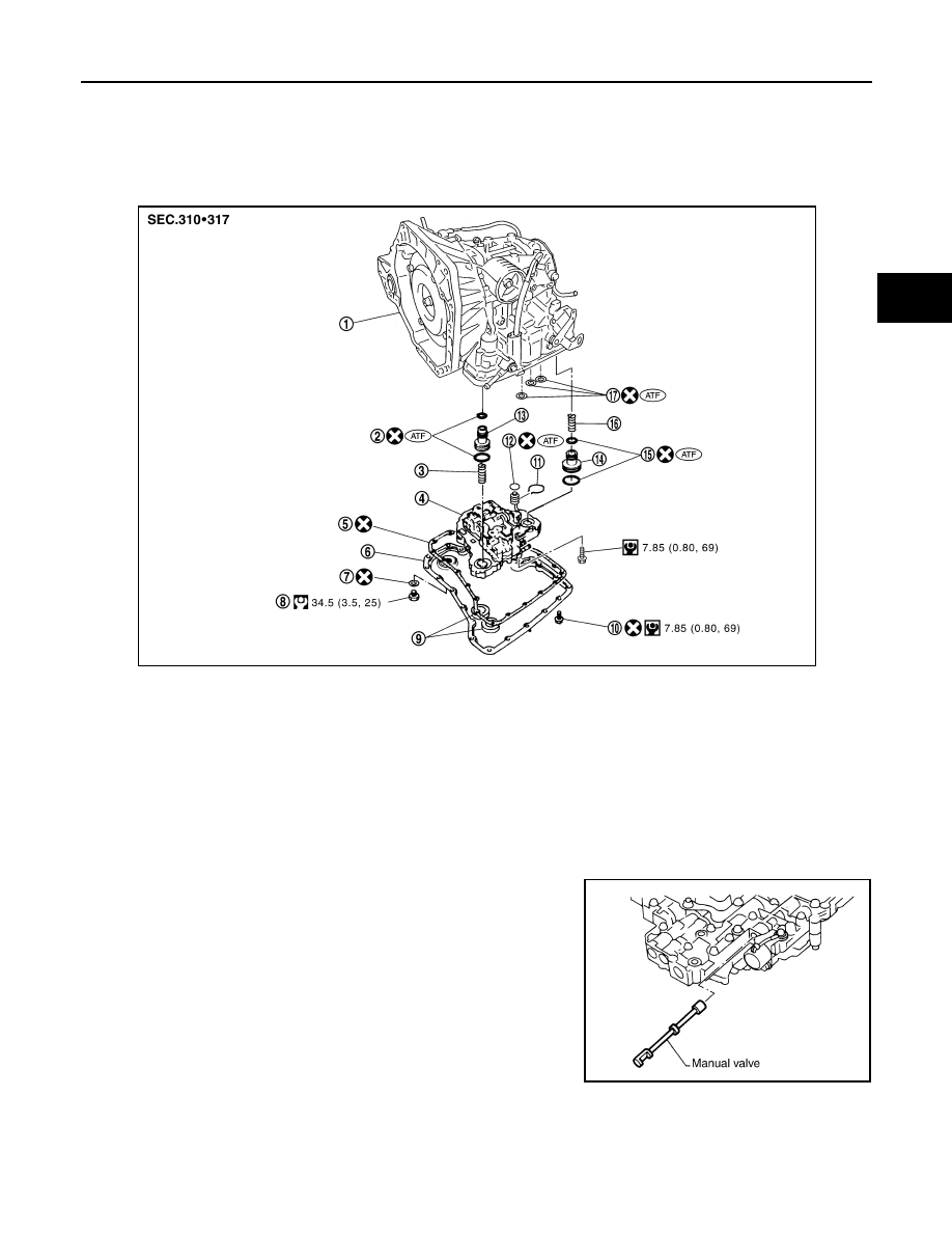
COMPONENTS

REMOVAL

Refer to the figure for control valve assembly and accumulators removal procedure.

CAUTION:

• Do not drop manual valve and servo release accumulator

return spring.

1.

A/T

2.

O-ring

3.

Return spring

4.

Control valve assembly

5.

Oil pan gasket

6.

Oil pan

7.

Drain plug gasket

8.

Drain plug

9.

Magnet

10. Oil pan fitting bolt

11.

Snap ring

12. O-ring

13. Servo release accumulator piston

14. N-D accumulator piston

15. O-ring

16. Return spring

17. Lip seal

SCIA6216J

SCIA3150E

TM-192

< ON-VEHICLE REPAIR >

[TYPE 1 (4AT: RE4F03B)]

CONTROL SYSTEM

• Check for foreign materials in oil pan to help determine causes of

malfunction. If the ATF is very dark, smells burned, or contains for-
eign particles, frictional material (clutches, band) may need
replacement. A tacky film that will not wipe clean indicates varnish
build up. Varnish can cause valves, servo, and clutches to stick
and can inhibit pump pressure. 

If frictional material is detected, flush the A/T fluid cooler after

repair of A/T. Refer to 

TM-172, "A/T Fluid Cooler Cleaning"

.

• Remove servo release accumulator piston and N-D accumulator

piston by applying compressed air if necessary.

CAUTION:

Hold each piston with lint-free paper.

- Apply compressed air to the oil hole as shown, and remove servo

release accumulator piston from transaxle case.

CAUTION:

Strong flow of air will push the accumulator piston out along
with a splash of ATF. Cover the area with lint-free paper and
blow air little by little to avoid this.

- Apply compressed air to the oil hole as shown, and remove N-D

accumulator piston and return spring from transaxle case.

CAUTION:

Strong flow of air will push the accumulator piston out along
with a splash of ATF. Cover the area with lint-free paper and
blow air little by little to avoid this.

SCIA3476E

SCIA4854E

SAT019DA

SAT020D

CONTROL SYSTEM

TM-193

< ON-VEHICLE REPAIR >

[TYPE 1 (4AT: RE4F03B)]

C

E

F

G

H

I

J

K

L

M

A

B

TM

N

O

P

- Remove O-rings (1) from servo release accumulator piston (2) and

N-D accumulator piston (3).

CAUTION:

Wrap the removed servo release accumulator piston (2) and
N-D accumulator piston (3) in a lint-free paper.

INSPECTION

• Inspect the sliding surfaces of each accumulator piston and tran-

saxle case, and replace if damaged or dented.
(1): Servo release accumulator piston
(2): N-D accumulator piston

• Inspect the sliding surfaces of manual valve and valve body, and

replace if damaged or dented.

• Inspect each return spring, and replace if damaged, deformed or

worn. Refer to 

TM-321, "Accumulator"

 for free length (L

1

) and

length (L

2

).

(1): Return spring (Servo release accumulator)
(2): Return spring (N-D accumulator)

CAUTION:

Do not remove spring retainer (3).

INSTALLATION

Install is in the reverse order of removal.

CAUTION:

• Completely remove all moisture, oil and old gasket, etc. from the oil pan gasket mounting surface of

transaxle case and oil pan.

• Do not reuse O-rings, lip seals, oil pan gasket and oil pan bolts.
• Apply ATF to manual valve, O-rings, lip seals and sliding surfaces transaxle case.

SCIA6033J

SCIA6035J

SCIA6955E

TM-194

< ON-VEHICLE REPAIR >

[TYPE 1 (4AT: RE4F03B)]

CONTROL SYSTEM

• Install bolts (A), (B) and (C) in control valve assembly.

• Set manual shaft in “N” position, then align manual plate (1) with

groove in manual valve (2).

• After installing control valve assembly to transaxle case, make

sure that selector lever can be moved to all positions.

• After completing installation, check for A/T fluid leakage and A/T

fluid level. Refer to 

TM-171, "Checking A/T Fluid"

.

Bolt symbol

A

B

C

Bolt length “

” mm (in)

40.0

(1.575)

33.0

(1.299)

43.5

(1.713)

Number of bolts

5

6

2

SCIA5911J

SCIA7090E


содержание   ..  1283  1284  1285  1286   ..