Mitsubishi Eclipse Cross (2023 year). Manual in english - page 10
Tire pressure monitoring system (TPMS)
z A window tint that affects the radio wave
3. Press the
switch or
switch to
CAUTION
signals is installed.
select the “ID 1” or “ID 2”, and then press
z The use of non-genuine wheels will prevent
the proper fit of the tire inflation pressure
and hold the
switch for approximately
NOTE
sensors, resulting air leakage or damage of
3 seconds or more to confirm the setting.
z Tire inflation pressures vary with the ambi-
the sensors.
ent temperature. If the vehicle is subjected to
large variations in ambient temperature, the
tire inflation pressures may be under-inflated
5
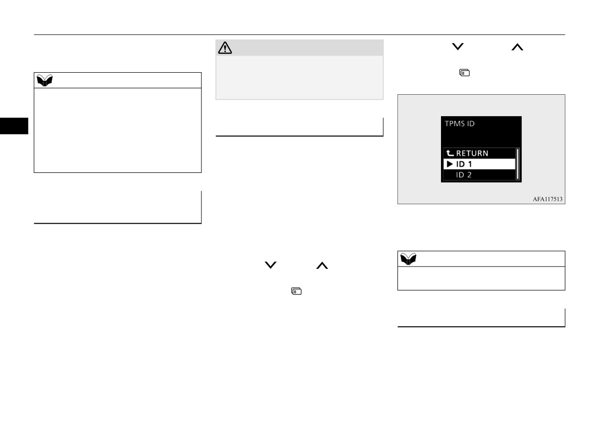
Tire ID set change
(causing the warning light / display come on)
N00584300042
when the ambient temperature is relatively
low. If the warning light / display comes on,
In case that 2 sets of tire inflation pressure
adjust the tire inflation pressure.
sensor ID are registered in the receiver, the
valid tire ID set can be changed by following
procedure.
Whenever the tires and wheels
1. Switch to the function setting screen.
are replaced with new ones
Refer to
“Multi-information display
4. The valid tire ID set is changed, and the
N00532900081
switches” on page 5-145.
number of the tire pressure monitoring
If new wheels with new tire inflation pressure
Refer to “Changing the function settings”
system (TPMS) SET indicator is changed.
sensors are installed, their ID codes must be
on page 5-155.
programmed into the tire pressure monitoring
NOTE
2. Press the
switch or
switch several
system. Have tire and wheel replacement per-
z The tire ID set is NOT changed, in case that
times to switch to the “TPMS ID” screen.
formed by an authorized Mitsubishi Motors
only 1 set of ID is registered.
Then, press the
switch to the setting
dealer to avoid the risk of damaging the tire
selection screen.
inflation pressure sensors. If the wheel
replacement is not done by an authorized
General information
Mitsubishi Motors dealer, it is not covered by
N00533001233
your warranty.
Your tire pressure monitoring system oper-
ates on a radio frequency subject to Federal
Communications Commission (FCC) Rules
(For vehicles sold in U.S.A.) and Industry
Canada Rules (For vehicles sold in Canada).
This device complies with part 15 of FCC
5-130
Features and controls

Rear-view camera
Rules and Industry Canada licence-exempt
WARNING
CAUTION
RSS standard(s).
z
Never rely solely on the rear-view camera
z
If the camera lens gets dirty, a clear image
Operation is subject to the following two con-
to clear the area behind your vehicle.
cannot be obtained. As necessary, rinse the
ditions.
Always check visually behind and all
lens with clean water and gently wipe with a
around your vehicle for persons, animals,
clean, soft cloth.
z This device may not cause harmful inter-
obstructions or other vehicles. Failure to
z
To avoid damaging the camera;
ference.
do so can result in vehicle damage, serious
• Do not rub the cover excessively or polish
z This device must accept any interference
injury or death.
it by using an abrasive compound.
received, including interference that may
5
z
The rear-view camera is an aid system for
• Do not disassemble the camera.
cause undesired operation.
backing up, but it is not a substitute for
• Do not splash hot water directly on the lens.
your visual confirmation.
• Do not spray the camera and its surround-
z
The view on the screen is limited, and
CAUTION
ings with high-pressure water.
objects outside the view, such as under the
z Changes or modifications not expressly
• Make sure that the liftgate
is
securely
bumper or around either corner of the
approved by the manufacturer for compli-
closed when backing up.
bumper end, cannot be seen on the screen.
ance could void the user’s authority to oper-
ate the equipment.
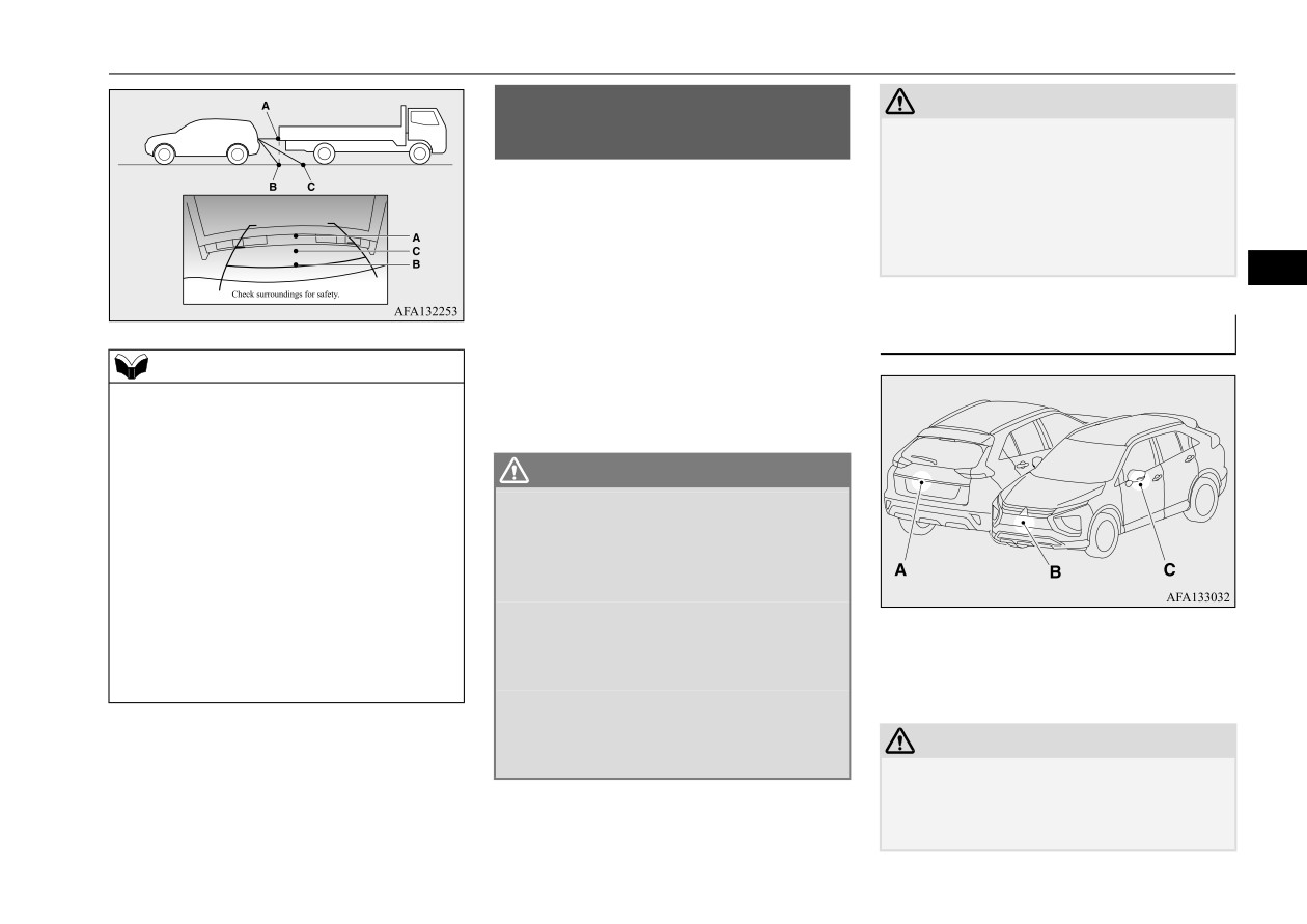
Location of rear-view camera
Rear-view camera
The rear-view camera (A) is in the liftgate, at
N00546201457
the left side of the liftgate handle.
When the selector lever is in the
“R”
(REVERSE) position with the ignition switch
in the “ON” position or the operation mode in
ON, the rear-view image will be displayed on
the screen of the Smartphone-link Display
Audio (SDA) or the Smartphone-link Display
Audio (SDA) navigation system.
When the selector lever is shifted out of the
“R”
(REVERSE) position, the rear-view
image will go off.
Features and controls
5-131
Rear-view camera
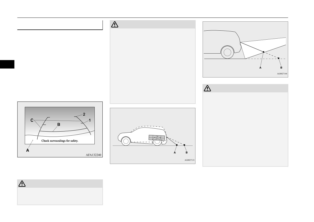
Reference lines on the screen
CAUTION
Case 2
z
Actual distance may be different from dis-
Reference lines and upper surface of the rear
tance indicated by the lines on the screen,
bumper (A) are displayed on the screen.
depending on the loading condition of the
vehicle and road surface condition.
z
Red line
(B) indicates approximately
The reference lines for distance and vehicle
20 inches (50 cm) behind the rear bumper.
width are based on a level, flat road surface.
z
Two Green lines (C) indicate approxi-
In the following cases, objects shown on the
5
screen will appear to be farther off than they
A- Actual objects
mately 8 inches (20 cm) outside of the
actually are.
B- Objects shown on the screen
vehicle body.
• When the rear of the vehicle is weighed
z
Short transverse lines (1 and 2) indicate
down with the weight of passengers and
approximate distance from the rear bum-
luggage in the vehicle. (Case 1)
CAUTION
per.
• When there is an upward slope at the back.
z
The reference lines for distance and vehicle
(Case 2)
width are intended to indicate the distance to
a flat object such as a level, flat road surface.
Case 1
They may not indicate correct distance
depending on the shape of an obstacle.
For example, when there is an object behind
the vehicle that has upper sections projecting
in the direction of the vehicle, the reference
lines on the screen will indicate that point A
is the farthest point and point B is the closest
point to the vehicle. In reality, point A and B
A- Actual objects
are actually the same distance from the vehi-
B- Objects shown on the screen
cle, and point C is farther off than point A
1-
Approximately 39 inches (100 cm)
and B.
2-
Approximately 79 inches (200 cm)
CAUTION
z The rear-view camera uses a wide-angle
lens. As a result, images and distances shown
on the screen are not exact.
5-132
Features and controls
Multi Around Monitor (if so equipped)
Multi Around Monitor (if so
CAUTION
z Before using the Multi Around Monitor,
equipped)
make sure that all doors and the liftgate are
N00587200101
closed and the outside mirrors are unfolded.
If an outside mirror is folded and/or if a front
The Multi Around Monitor system uses four
door and/or the liftgate is open, the areas dis-
cameras,
“Front-view camera”,
“Side-view
played on the Multi Around Monitor will not
cameras
(right and left)” and
“Rear-view
be appropriate.
camera”, and displays composite views from
5
those cameras on the Smartphone-link Dis-
play Audio (SDA) or the Smartphone-link
Location of each camera
Display Audio (SDA) navigation system.
NOTE
The Multi Around Monitor system will assist
z
Mirror image is displayed on the screen.
the driver to park the vehicle in a narrow or
z
On vehicles equipped with the SDA or the
parallel parking space.
SDA navigation system, it is possible to
change the display language of the screen.
WARNING
For details, please refer to the separated
z
Before using the Multi Around Monitor
owner’s manual.
system, read this entire section to fully
z
Under certain circumstances, it may become
understand the limitations of this system.
difficult to see an image on the screen, even
Failure to follow instructions could result
when the system is functioning correctly.
in an accident.
• In a dark area, such as at night.
z
The Multi Around Monitor system is an
• When water drops or condensation are on
aid system to help observe around the
A- Rear-view camera
the lens.
vehicle. It is not a substitute for your
B- Front-view camera
• When sun light or headlights shine directly
visual confirmation.
C- Side-view camera
into the lens.
z
Never rely solely on the Multi Around
Monitor system. The view on the screen is
limited, and objects outside the view can-
CAUTION
not be seen on the screen.
z If the camera lens gets dirty, a clear image
cannot be obtained. As necessary, rinse the
lens with clean water and gently wipe with a
clean, soft cloth.
Features and controls
5-133
Multi Around Monitor (if so equipped)
CAUTION
z To avoid damaging the camera;
• Do not rub the cover excessively or polish
it by using an abrasive compound.
• Do not disassemble the camera.
• Do not splash hot water directly on the lens.
• Do not spray the camera and its surround-
5
ings with high-pressure water.
• Make sure that the liftgate is securely
closed when backing up.
z Do not attach anything on the camera and/or
surrounding areas. Doing so will disturb the
camera.
5-134
Features and controls

Multi Around Monitor (if so equipped)
Range of view of the Multi Around Monitor
N00587300056
The range of view of the Multi Around Monitor cameras is limited to the area shown in the illustrations. It cannot show around the both sides and
the lower part of the front and rear bumpers, etc. While driving, be sure to visually confirm safety around the vehicle.
Range of view of the Multi Around Monitor cameras
5
A: Front-view camera
B: Side-view camera (Right)
C: Side-view camera (Left)
D: Rear-view camera
Features and controls
5-135
Multi Around Monitor (if so equipped)
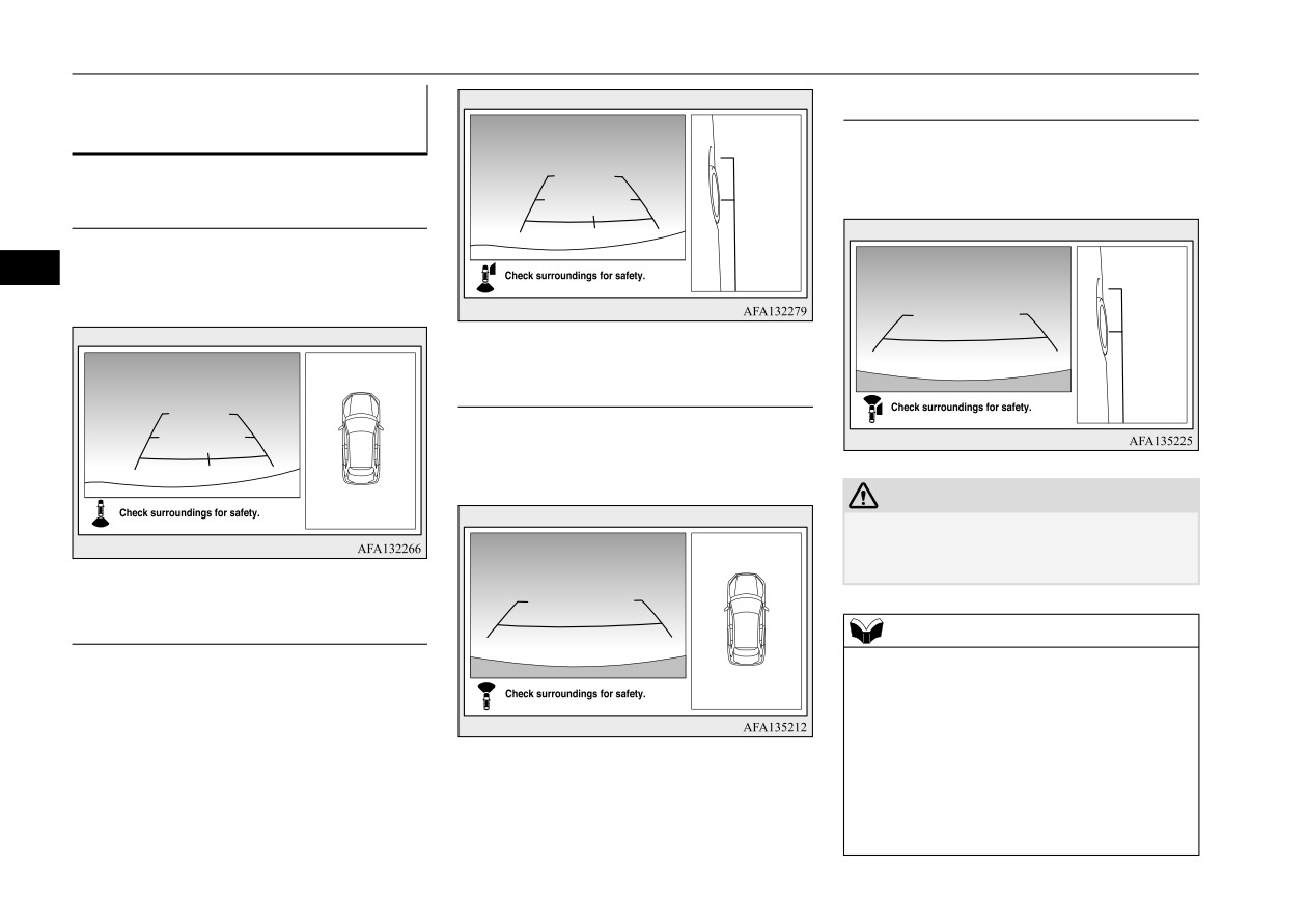
Types of views of the Multi
Side-view/Front-view mode
Around Monitor
N00587400099
Views of the passenger’s side of the vehicle
and the front of the vehicle are displayed.
Bird’s eye-view/Rear-view mode
Views of the surroundings of the vehicle and
5
behind the vehicle are displayed.
Bird’s eye-view/Front-view mode
Views of the surroundings of the vehicle and
the front of the vehicle are displayed.
CAUTION
z The camera uses a special lens. As a result,
images and distances shown on the screen
are not exact.
Side-view/Rear-view mode
NOTE
z Because the cameras have a special lens, the
Views of the passenger’s side of the vehicle
lines on the ground between parking spaces
and behind the vehicle are displayed.
may not look parallel on the screen.
z Under certain circumstances, it may become
difficult to see an image on the screen, even
when the system is functioning correctly.
• In a dark area, such as at night.
• When water drops or condensation are on
the lens.
5-136
Features and controls
Multi Around Monitor (if so equipped)
NOTE
NOTE
Switching of the screen (Selector
• When sun light or headlights shine directly
z The passenger’s side screen can be switched
lever is “R” (REVERSE))
into the lens.
to the side-view by pressing the camera
• When a fluorescent light shines directly
switch on the steering wheel.
If the camera switch is pressed, the mode of
into the lens.
Multi Around Monitor is switched as follows.
z
If the atmospheric temperature is extremely
Bird’s eye-view/Rear-view mode
Side-
hot or extremely cold, the camera images
Operation with the switch
view/Rear-view mode
may not be clear.
5
There is no abnormality.
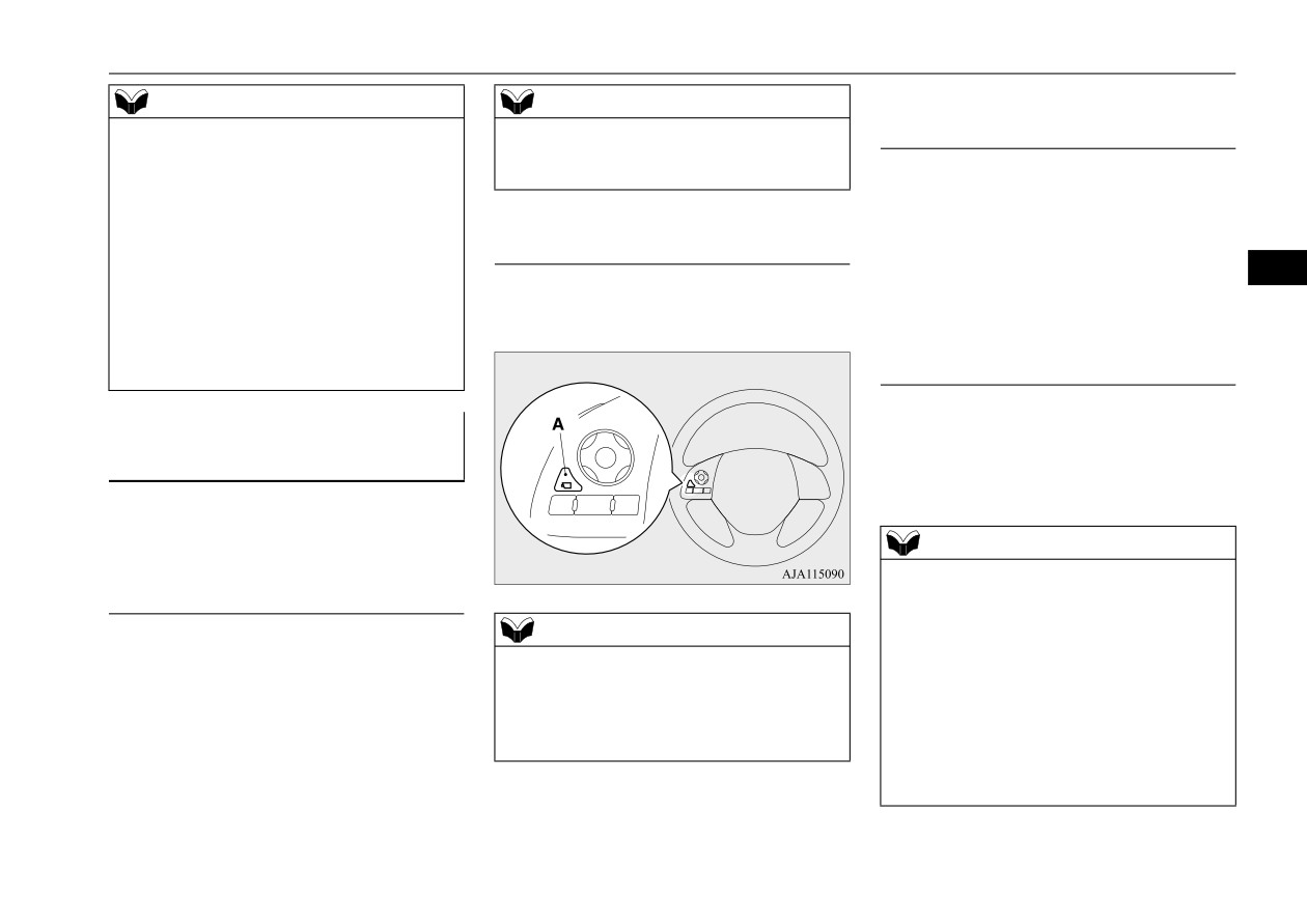
When the camera switch (A) is pressed, the
z
If a wireless device is installed near the cam-
bird’s eye-view/front-view is displayed.
Switching of the screen (Selector
era, the camera images may cause electrical
lever is other than “R”
system interference and the system may stop
(REVERSE))
functioning properly.
If the camera switch is pressed, the mode of
How to use the Multi Around
Multi Around Monitor is switched, Bird’s
Monitor
eye-view/Front-view mode
Side-
N00587500104
view/Front-view mode OFF
The Multi Around Monitor can only be used
when the operation mode is put in ON.
NOTE
z When you move the selector lever to the “R”
Operation with the selector lever
(REVERSE) position with the front-view
mode displayed on the driver’s side screen,
NOTE
the driver’s side screen switches to the rear-
When you move the selector lever to the “R”
z
If there is no operation for 3 minutes after
view mode. When you shift the selector lever
(REVERSE) position, the bird’s eye-
the Multi Around Monitor is displayed by
to any other position, the driver’s side screen
view/rear-view is displayed on the SDA or
pressing the switch with the selector lever in
switches to the front-view mode.
the SDA navigation system. When you move
other than “R” (REVERSE), the display dis-
z When the camera switch is pressed at the
the selector lever to any other position, the
appears.
vehicle speed of approximately
6 mph
display disappears.
(10 km/h) or higher, only the side-view can
be displayed on the passenger’s side screen.
Features and controls
5-137

Multi Around Monitor (if so equipped)
z
The Two Green lines (C) indicate the
NOTE
NOTE
approximate vehicle width.
z The front-view will not be displayed when
z
The Orange lines
(D) indicates an
the vehicle speed exceeds approximately
expected course when the vehicle moves
6 mph (10 km/h).
forward with the steering wheel turned. It
z The display of the view may be delayed dur-
disappears when the steering wheel is in
ing switching of the screen.
the neutral position.
z
The approximate distance from the vehi-
5
How to read the screen
cle body is as follows:
N00587600088
In any mode other than the Bird’s eye-view
mode, the lines in the screen give the follow-
Rear-view mode
ing information. Use them only as a guide.
N00587700063
Reference lines for the distance and the vehi-
CAUTION
cle width and upper surface of the rear bum-
z If the camera and/or its surrounding area
per (A) are displayed on the screen.
have experienced an impact, the Multi
Around Monitor system may not function
z
The Red line (B) indicates approximately
correctly. Have the vehicle inspected by an
20 inches (50 cm) behind the rear edge of
authorized Mitsubishi Motors dealer.
the rear bumper.
z
The Two Green lines (C) indicate the
1-
Approximately 39 inches (100 cm) from
approximately vehicle width.
the front edge of the front bumper
Front-view mode
z
The Orange line (D) indicates an expected
course when the vehicle is reserved with
Reference lines for the distance and the vehi-
NOTE
the steering wheel turned. It disappears
when the steering wheel is in the neutral
cle width and upper surface of the front bum-
z
When the expected course lines are dis-
per (A) are displayed on the screen.
played in the front-view, the expected course
position.
lines are also displayed in the bird’s eye-
z
The approximate distance from the vehi-
z The Red line (B) indicates approximately
view (Front: solid line, Rear: broken line).
cle body is as follows:
20 inches (50 cm) from the front edge of
the front bumper.
5-138
Features and controls

Multi Around Monitor (if so equipped)
CAUTION
CAUTION
For example;
• When there is a downward slope behind the
In the following cases, objects shown on the
vehicle, objects shown on the screen will
screen will appear to be farther off than they
appear to be closer than they actually are.
actually are.
• When the rear of the vehicle is weighed
down with the weight of passengers and
luggage in the vehicle.
5
1- Approximately
39 inches
(100 cm)
from the rear edge of the rear bumper
2- Approximately
79 inches
(200 cm)
from the rear edge of the rear bumper
A: Actual objects
B: Objects shown on the screen
CAUTION
A: Actual objects
z
The rear-view camera uses a wide-angle
B: Objects shown on the screen
lens. As a result, images and distances shown
on the screen are not exact.
• When there is an upward slope behind the
vehicle.
z
Never rely solely on the reference lines. The
reference lines indicating distance and vehi-
cle width are based on a level, flat road sur-
face.
Actual distance may be different from dis-
tance indicated by the lines on the screen,
depending on the loading condition of the
vehicle and road surface condition.
Also, your vehicle width indicated by the
reference lines may be different from the
actual vehicle width.
A: Actual objects
B: Objects shown on the screen
Features and controls
5-139

Multi Around Monitor (if so equipped)
CAUTION
CAUTION
NOTE
• When the vehicle is approaching a truck,
• When there is an object behind the vehicle
z When the expected course lines are dis-
the reference lines indicate that your vehi-
that has upper sections projecting in the
played in the rear-view, the expected course
cle will clear the truck. In reality, the truck
direction of the vehicle, the reference lines
lines are also displayed in the bird’s eye-
is in your path.
on the screen will indicate that point A is
view (Front: broken line, Rear: solid line).
the farthest point and point B is the closest
point to the vehicle. In reality, point A and
B are actually the same distance from the
5
vehicle, and point C is farther off than point
A and B.
5-140
Features and controls

Multi Around Monitor (if so equipped)
Side-view mode
Bird’s eye-view mode
CAUTION
N00587900036
N00588000047
z
The bird’s eye-view is a composite image
Reference lines for the vehicle width and the
An overhead view in which the vehicle is
from images captured by the
“Front-view
front end of the vehicle are displayed on the
looked down is displayed so that you can eas-
camera”,
“Side-view cameras
(right and
screen.
ily identify the location of your vehicle and
left)” and “Rear-view camera”. As a result,
the course to enter the parking space.
objects may appear to be farther away than
1- Approximate vehicle width including
they actually are. Also, an object may appear
the door mirror.
to be in a direction and/or location different
5
from actual. In addition, blind spots exist in
2- Approximate location of the axle center
proximity of the vehicle.
of the front wheel.
Even if the screen indicates that there is a
3- Approximate 20 inches (50 cm) from the
space between your vehicle and an object,
front edge of the front bumper.
there may actually be less or no space.
Always check visually behind and all around
your vehicle.
z
The view at a section near each corner on the
Bird's eye-view is combined from the edge
of the view captured by each camera. As
result, an object indicated in the section may
be unclear, and it may disappear/reappear on
the screen.
NOTE
z In the Bird’s eye-view mode, since the views
captured by the four cameras, “Front-view
camera”,
“Side-view cameras
(right and
left)” and “Rear-view camera” are processed
based on a level flat road surface, an image
may be displayed as follows:
• An object appears to have fallen down and
looks longer or larger.
Features and controls
5-141

Instrument cluster
2. Press the switch (A) to display the bird’s
NOTE
NOTE
eye-view/front-view.
• An object having a height from the road
• When you place the gearshift lever or the
surface may seem to appear from the joint
selector lever in the “R” (REVERSE) posi-
of the view composition processing
tion.
regions.
• When you do not operate anything for 30
z
The brightness of the views from each cam-
seconds.
era may vary depending on the illuminance
• The operation mode is put in OFF.
conditions.
5
z
An object above the camera is not displayed.
Instrument cluster
z
The object displayed in the Front-view mode
or the Rear-view mode may not be displayed
N00519001444
in the Bird’s eye-view mode.
z
The view in the Bird’s eye-view mode may
be displaced from its true position when the
3. Press and hold down the switch (A) until
mounting location and angle of each camera
the vehicle icon blinks to enter the selec-
are changed.
tion mode of the vehicle icon color in the
z
The lines on the road may appear to be dis-
bird’s eye-view.
placed or bent at the joint of the views.
4. Press the switch until the desired color
appears on the display.
To change the vehicle icon color
Each time you press the switch, the vehi-
in the bird’s eye-view
cle icon color in the bird’s eye-view will
N00594200028
change to the next one.
1-
Tachometer P.5-143
5. When it is changed to your desired color,
It is possible to change the vehicle icon color
2-
Multi-information display
press and hold the switch (A) for a few
in the bird’s eye-view.
P.5-144
seconds. This completes the setting.
Information screen display
list
1. Stop the vehicle in a safe place.
P.5-165
NOTE
3-
Speedometer P.5-143
CAUTION
4-
Rheostat illumination button
z When the selection mode is in the following
z For reasons of safety, do not operate the
P.5-143
situations, the vehicle icon color does not
switch while driving.
change.
5-142
Features and controls

Instrument cluster
Speedometer
Tachometer
Meter illumination control
N00519101272
N00519201303
N00554901349
The speedometer shows the vehicle speed in
The tachometer shows engine revolutions per
Each time you press this button, there is a
miles per hour (mph) or kilometers per hour
minute. This allows the driver to determine
sound and the brightness of the instruments
(km/h).
the most efficient selector position and engine
changes.
speed combinations.
This gauge also assists in evaluating engine
Type A
performance.
5
1- Brightness level
2- Rheostat illumination button
Type B
NOTE
CAUTION
z You can adjust to 8 different levels for when
z The red zone indicates an engine speed
the front side-marker lights are illuminated
beyond the range of safe operation.
and when they are not.
Select the correct selector position to control
z If the vehicle is equipped with the automatic
the engine speed so that the tachometer indi-
light control, the light switch is in the “
”,
cator does not enter the red zone.
“
”, or “AUTO” position and it is suffi-
ciently dark outside the vehicle, the meter
illumination switches automatically to the
adjusted brightness.
Features and controls
5-143
Multi-information display
position, average and instant fuel consump-
NOTE
tion, driving range, average speed, etc.
z
The brightness level of the instruments is
stored when the ignition switch is turned to
It is also possible to change elements such as
the “OFF” position or the operation mode is
the language and units used on the multi-
put in OFF.
information display.
z
If you press and hold the button for longer
than approximately 2 second when the front
[With the ignition switch
or the
operation
side-marker lights
are illuminated, the
5
mode in OFF]
brightness level changes to the maximum
level. Pressing and holding the button for
longer than approximately 2 second again
returns the brightness level to the previous
level.
It is recommended to use this function when
it is difficult to read the meter due to the
meter illumination is dimmed by turning on
the tail lights in bright areas.
For vehicles equipped with the Smartphone-
link Display Audio
(SDA) or the Smart-
phone-link Display Audio (SDA) navigation
system, the operation of the screen back-
ground theme and the switch illumination
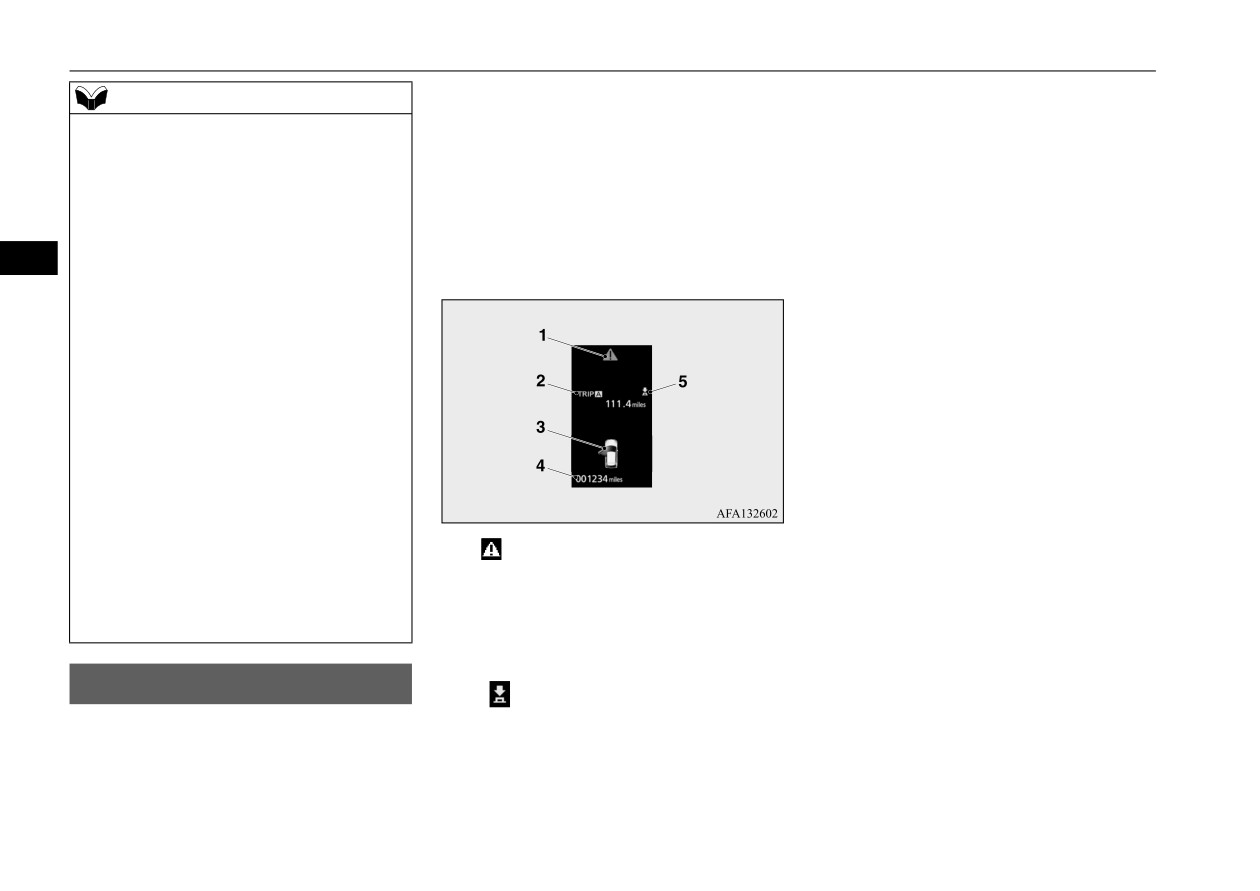
1-
Warning display screen P.5-149
when the meter illumination brightness level
2-
Information screen P.5-146
is changed to the maximum vary depending
Interrupt display screen P.5-149
on the specifications of the SDA or the SDA
3-
Door ajar warning display screen
navigation system.
P.5-150
4-
Odometer P.5-151
Multi-information display
5-
“
” mark indicator P.5-149
N00555001549
The multi-information display displays warn-
ings, the odometer, trip odometer, service
reminder, engine coolant temperature, fuel
remaining, outside temperature, selector lever
5-144
Features and controls

Multi-information display
[With the ignition switch or the operation mode in ON]
5
1-
S-AWC drive mode display screen (if
10- ECO indicator P.5-154
Multi-information display
so equipped) P.5-71
11-
“
” mark indicator P.5-149
switches
2-
Warning display screen P.5-149
12- Fuel remaining display screen
N00555101234
3-
ECO mode indicator display screen
P.5-150
Each time the multi-information display
P.5-204
13- Outside temperature display screen
switches are operated, the buzzer sounds and
4-
Information screen P.5-146
P.5-151
the multi-information display changes
5-
Selector lever position display
between information such as warnings, trip
P.5-65
NOTE
odometer, average and instant fuel consump-
6-
Engine coolant temperature display
z The fuel units, outside temperature units,
tion, distance range.
P.5-150
display language, and other settings can be
It is also possible to change elements such as
7-
Odometer P.5-151
changed.
the language and units used on the multi-
8-
Cruise control display screen P.5-87
Refer to “Changing the function settings” on
information display by operating the multi-
page 5-155.
9-
Adaptive Cruise Control System (ACC)
information display switches.
display screen (if so equipped)
P.5-92
Features and controls
5-145

Multi-information display
5
Information screen (With the ignition switch in “OFF” position or the operation mode in OFF)
N00555301207
Press the
switch to display the information screen. Then, press the
switch or
switch to switch the display screen in the following order.
*: When there is a warning display
1- Trip odometer
P.5-151
5-146
Features and controls
Multi-information display
2- Trip odometer
P.5-151
3- ECO score display P.5-155
4- Service reminder P.5-151
5- Redisplay of a warning display screen P.5-149
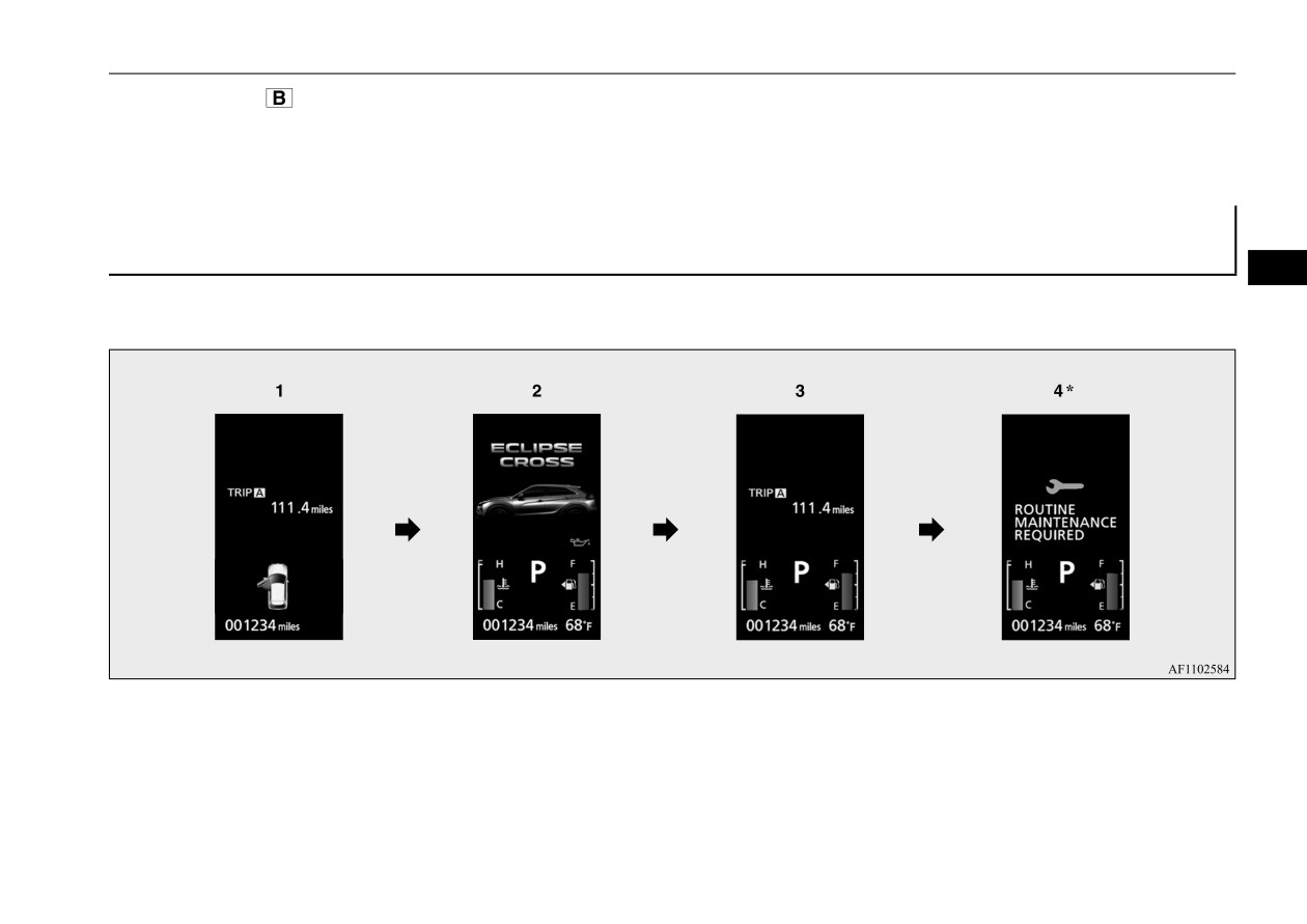
Information screen (With the ignition switch is turned from the “OFF” position to the “ON” position
or the operation mode is changed from OFF to ON)
5
N00555801345
When the ignition switch is turned to the “ON” position or the operation mode is put in ON, the display screen switches in the following order.
*: When the inspection time has arrived
1- Screen when the ignition switch or the operation mode is OFF
2- System check screen P.5-153
3- Screen when the ignition switch or the operation mode is ON
4- Service reminder P.5-151
Features and controls
5-147

Multi-information display
Information screen (With the ignition switch or the operation mode in ON)
N00556201346
Press the
switch or
switch to switch the display screen in the following order.
5
*: When there is a warning display
5- Average speed display P.5-154
10- Function setting screen P.5-155
Instant fuel consumption display
11- Redisplay of a warning display screen
1- Trip odometer
P.5-151
P.5-154
P.5-149
2- Trip odometer
P.5-151
6- ECO score display P.5-155
3- Driving range display P.5-153
7- AYC (Active Yaw Control) operation
NOTE
ECO drive assist display P.5-154
display (if so equipped) P.5-81
z While driving, the service reminder are not
4- Average fuel consumption display
8- S-AWC operation display
(if so
displayed even if you operate the multi-
P.5-153
equipped) P.5-72
information display switches. Always stop
ECO drive assist display P.5-154
9- Service reminder P.5-151
the vehicle in a safe place before operating.
5-148
Features and controls

Multi-information display
NOTE
Returning to the display screen from
Redisplay of a warning display
z
While driving, the function setting screen is
before the warning display
screen
not displayed even if you operate the multi-
N00579600034
Even if the cause of the warning display is
information display switches.
Always park the vehicle in a safe place,
not eliminated, you can return to the screen
When the
warning is displayed, if you
firmly apply the parking brake and put the
that was displayed before the warning dis-
press the
switch or
switch a few
selector lever into the “P” (PARK) position
play.
times, the warning display screen you
before operating the function setting screen.
switched from is redisplayed.
5
Refer to “Changing the function settings” on
If you press the
switch, the display screen
page 5-155.
switches to the screen display from before the
z
When there is information to be announced,
Other interrupt displays
warning and the
warning (A) is also dis-
N00579700022
such as a system fault, the tone sounds and
the screen display is switched.
played.
The operation status of each system is dis-
Refer to “Interrupt display screen” on page
played on the information screen.
5-149.
For further details, refer to the appropriate
page in the warning display list.
Interrupt display screen
Refer to “Other interrupt displays” on page
N00556301246
5-182.
Warning display
warning display screen
N00555201248
When there is information to be announced,
such as a system fault, the tone sounds and
This is displayed when you press the
the information screen is switched to the
switch and return from the warning display
warning display screen.
screen to the previous screen.
If you want to switch the display
Refer to the warning list and take the neces-
This mark is also displayed if there is another
sary measures.
warning other than the one displayed.
Warning display screens with the “
” mark
Refer to
“Warning display list” on page
When the cause of the warning display is
displayed in the upper right of the screen can
5-166.
eliminated, the
warning goes out automat-
be switched. If you want to switch the dis-
When the cause of the warning display is
ically.
eliminated, the warning display goes out
play, press the
switch for approximately
automatically.
2 seconds or more.
Features and controls
5-149

Multi-information display
NOTE
CAUTION
z Always make sure that the warning display
z When the warning is displayed, the warn-
goes out before beginning to drive.
ing display screen can be redisplayed on the
information screen.
Refer to “Information screen (with the igni-
tion switch in “OFF” position or the opera-
Engine coolant temperature
tion mode in OFF)” on page 5-146.
display
5
Refer to “Information screen (with the igni-
N00578200020
tion switch or the operation mode in ON)” on
page 5-148.
Shows the engine coolant temperature.
If the coolant becomes hot, “
” will blink.
F- Full
Pay careful attention to the engine coolant
E- Empty
Door ajar warning display
temperature display while you are driving.
screen
CAUTION
N00529700056
CAUTION
z
Running out of gas could damage the cata-
z If the engine is overheating, “
” will blink.
lytic converter. If the warning display
In this case, the bar graph is on the red zone.
appears, refuel immediately.
Immediately park the vehicle in a safe place
and take the required measures. Refer to
“Engine overheating” on page 8-4.
NOTE
If any of the doors or the liftgate is not com-
z
It may take several seconds to stabilize the
display after refilling the tank.
pletely closed, this displays the open door or
Fuel remaining display screen
z
If fuel is added with the ignition switch or
liftgate.
N00556601252
the operation mode in ON, the remaining
If the speed increases to approximately 5 mph
fuel display may incorrectly indicate the fuel
(8 km/h) or higher with a door ajar, a tone
Shows the amount of fuel remaining.
level.
will sound four times to inform you that a
z
The arrow (A) indicates that the fuel tank
door is ajar.
filler door is located on the left side of the
vehicle. (Refer to “Filling the fuel tank” on
page 3-3.)
5-150
Features and controls

Multi-information display
more. Only the currently displayed value will
Fuel remaining warning display
NOTE
be reset.
N00578300106
z The display setting can be changed to the
When the fuel level runs low, the information
preferred units (°F or °C).
Example
Refer to “Changing the function settings” on
screen switches to the interrupt display of the
If trip odometer
is displayed, only trip
page 5-155.
fuel remaining warning display and the mark
z Depending on factors such as the driving
odometer
will be reset.
(B) on the fuel remaining display flashes. If
conditions, the displayed temperature may
the warning display appears, refuel immedi-
vary from the actual outside temperature.
z Both trip odometers
and
can
ately.
5
count up to 9999.9 miles/kilometers.
When a trip odometer goes past
9999.9 miles/kilometers, it returns to
Odometer
0.0 miles/kilometers.
N00574901026
z When disconnecting the battery terminal,
Shows the total distance traveled.
the memories of trip odometer displays
and
are cleared, and their displays
Trip odometer
return to “0.0 miles/kilometers”.
N00575001079
Shows the distance traveled between two
Service reminder
points.
N00556701338
Usage examples for trip odometer
, trip
Displays the approximate time until the next
odometer
recommended periodic inspection.
“---” is
NOTE
It is possible to measure two currently trav-
displayed when the inspection time has
z
On hills or curves, the display may be incor-
eled distances, from home using trip odome-
arrived.
rect due to the movement of fuel in the tank.
ter
and from a particular point on the way
using trip odometer
Outside temperature display
screen
To reset the trip odometer
N00556501118
To return the display to “0”, hold down the
Shows the temperature outside the vehicle.
switch for approximately 2 seconds or
Features and controls
5-151