Mitsubishi Mirage G4 (2022 year). Manual in english - page 9

Loading information
This placard shows the maximum
Tire and loading information
number of occupants permitted to
placard
ride in your vehicle as well as “the
N00630101436
combined weight of occupants and
The tire and loading information
cargo” (A), which is called the vehi-
placard is located on the inside sill of
cle capacity weight. This placard also
the driver’s door.
tells you the size and recommended
inflation pressure for the original
6
equipment tires on your vehicle. For
more information, refer to “Tires” on
page 9-12.
6-8
Driving safety
Loading information
5. Determine the combined weight
Steps for Determining Correct
of luggage and cargo being loaded
Load Limit
on the vehicle. That weight may
N00630201280
not safely exceed the available
1. Locate the statement “The com-
cargo and luggage load capacity
bined weight of occupants and
calculated in Step 4.
cargo should never exceed XXX
6. If your vehicle will be towing a
kg or XXX lbs.” on your vehicle’s
trailer, load from your trailer will
placard.
6
be transferred to your vehicle.
2. Determine the combined weight
Consult this manual to determine
of the driver and passengers that
how this reduces the available
will be riding in your vehicle.
cargo and luggage load capacity
3. Subtract the combined weight of
of your vehicle.
the driver and passengers from
XXX kg or XXX lbs.
NOTE
4. The resulting figure equals the
z The above steps for determining
available amount of cargo and
correct load limit were written in
luggage load capacity. For exam-
accordance with U.S.A. regula-
ple, if the “XXX” amount equals
tions.
1400 lbs. and there will be five
Your vehicle cannot tow a
150 lbs. passengers in your vehi-
trailer, so step 6 is irrelevant.
cle, the amount of available cargo
and luggage load capacity is
650 lbs. (1400 - 750 (5 x 150) =
650 lbs.)
Driving safety
6-9

Loading information
NOTE
z The following table shows examples on how to calculate total cargo/load capacity of your vehicle with varying
seating configurations and number and size of occupants. This table is for illustration purposes only and may not
be accurate for the seating and load capacity of your vehicle.
z For the following example the combined weight of occupants and cargo should never exceed 865 lbs (392 kg).
6
6-10
Driving safety

Cargo loads
NOTE
z Under a maximum loaded vehicle condition, gross axle weight ratings (GAWR’s) for the front and rear axles
must not be exceeded. For further information on GAWR’s, vehicle loading, see the “Specifications” section of
this manual.
Cargo loads
WARNING
N00629700435
z Do not load cargo or luggage higher than
the top of the seatback. Be sure that your
cargo or luggage cannot move when your
6
Cargo load precautions
vehicle is in motion.
N00630300082
Having either the rear view blocked, or
To determine the cargo load capacity for your
your cargo being thrown inside the cabin
vehicle, subtract the weight of all vehicle
if you suddenly have to brake can cause a
occupants from the vehicle capacity weight.
serious accident or injury or death.
For additional information, if needed, refer to
z Put cargo or luggage in the cargo area of
your vehicle. Try to spread the weight
“Steps for Determining Correct Load Limit”
evenly.
on page 6-9.
WARNING
DO NOT USE the Gross Vehicle Weight Rat-
z
To reduce the risk of serious injury or
ing and Gross Axle Weight Rating numbers
Loading cargo on the roof
death, the combined weights of the driver,
listed on the safety certification label
(A)
N00630401149
passengers and cargo and must never
located on the inside sill of the driver’s door
exceed the vehicle capacity weight.
as the guide for passengers and/or cargo
WARNING
z
Exceeding the vehicle capacity weight will
weight.
z Weight placed on the roof of the vehicle
adversely affect vehicle performance,
will raise the vehicle’s center of gravity
including handling and braking, and may
and adversely affect its handling charac-
cause an accident.
teristics. As a result, driving errors or
emergency maneuvers could lead to a loss
of control and result in an accident. Drive
slowly and avoid excessive maneuvers
such as sudden braking or quick turning.
Driving safety
6-11

Trailer towing
WARNING
CAUTION
Trailer towing
z
Make sure that the weight of luggage and
z
Before driving and after traveling a short dis-
N00629801420
the roof carrier do not exceed the maxi-
tance, always check the load to make sure it
mum roof load, 110 lb (50 kg). If the maxi-
is securely fastened to the roof carrier.
mum roof load is exceeded, this could
Stop the vehicle periodically and check that
cause damage to the vehicle or result in an
the load remains secure. If the load is not
accident.
secure, it could fall from the vehicle and
z
The total weight of all occupants and lug-
damage your vehicle, another vehicle or cre-
gage, including your roof load, must not
ate a road hazard.
exceed the vehicle capacity weight. For
6
more information, refer to “Tire and load-
ing information placard” on page 11-3.
NOTE
z
Roof load is determined by adding the
z
To prevent wind noise or reduction in gas
weight of the roof carrier and the weight
mileage, remove the roof carrier when not in
of the luggage placed on the roof carrier.
use.
WARNING
z
Before using an automatic car wash, check
with the attendant to determine if the roof
z
Do not use this
vehicle for
CAUTION
carrier should be removed.
trailer towing. It may not be
z
Do not load luggage directly onto the roof.
z
Be sure that adequate clearance is main-
possible to maintain control or
Use a roof carrier that properly fits your
tained for raising the trunk lid during loading
vehicle.
luggage on the roof carrier.
adequate braking.
For installation, refer to the instruction man-
ual provided with the roof carrier.
z
Place the luggage on the carrier so that its
weight is distributed evenly with the heaviest
items on the bottom. Do not load items that
are wider than the roof carrier.
6-12
Driving safety
Comfort controls
Vents
7-2
Automatic air conditioning
7-4
Important air conditioning operating tips
7-10
Air purifier
7-11
Antenna
7-11
General information about your radio
7-12
7

Vents
Vents
N00729901347
1- Open
7
2- Close
Side vents
*: Optional equipment
1- Center vents
NOTE
When the dimple (A) is pressed, the vents
2- Side vents
open.
z On rare occasions, air from the vents of an
air-conditioned vehicle may be foggy. This is
To close the vents, press the dimple on the
only moist air cooling suddenly and does not
opposite side.
Air flow and direction adjust-
indicate a problem.
Change the direction of the air flow by turn-
z Do not let drinks or other liquids get into the
ments
ing the vent itself.
vents as they could prevent the air condition-
N00730200330
ing from operating normally.
Center vents
Move the knob (A) to make adjustments.
7-2
Comfort controls

Vents
Changing the mode selection
Foot/Face position
Foot/Defroster position
N00736401807
Air flows to the upper part of the passenger
Air flows to the leg area, the windshield and
To change air flow direction, press the
compartment, and flows to the leg area.
the door windows.
MODE switch or defogger switch. (Refer to
“MODE switch” on page 7-6, “Defogger
switch” on page 7-6.)
These symbols are used in the next several
illustrations to demonstrate the quantity of air
coming from the vents.
: Small amount of air from the vents
: Medium amount of air from the vents
7
: Large amount of air from the vents
Face position
Air flows only to the upper part of the passen-
Foot position
Defroster position
ger compartment.
Air flows mainly to the leg area.
Air flows mainly to the windshield and the
door windows.
Comfort controls
7-3

Automatic air conditioning
Automatic air conditioning
N00731501500
The air conditioning can only be used while the engine is running.
CAUTION
z The engine speed may increase when the air conditioning is operating.
With an increased engine speed, a CVT vehicle will creep to a greater degree than with a lower engine speed. Fully depress the brake pedal to prevent the
vehicle from creeping.
7
Control panel
N00711801624
Type 1
Type 2
1- Temperature control switch
4- Air selection switch
8- Electric rear window defogger switch
2- Air conditioning switch
5- Blower speed selection switch
P.5-104
3- MODE switch
6- Defogger switch
9- OFF switch
7- AUTO switch
10- Temperature display
7-4
Comfort controls
Automatic air conditioning
11- Mode selection display
NOTE
12- Air selection indicator
• The fan does not operate even after stop-
13- Air conditioning indicator
ping and restarting the engine or the fan
14- AUTO indicator
stops frequently.
15- Blower speed display
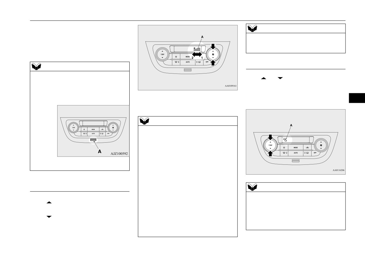
Temperature control switch
NOTE
N00737001406
z There is an interior air temperature sensor
Press
or
of the temperature control
(A) in the illustrated position.
switch to the desired temperature.
Never place anything over the sensor, since
doing so will prevent it from functioning
The selected temperature will be shown in the
1- Increase
properly.
display (A).
7
2- Decrease
NOTE
z
Due to a drop in the battery voltage or some
other problem, the blower speed may tempo-
rarily become less than the selected blower
speed display setting or the fan may stop.
If the fan stops, turn the ignition switch to
z A sound will be made every time you push
the
“OFF” position or put the operation
any of the switches.
mode in OFF, wait a few minutes, and then
turn the ignition switch back to the “ON”
position or put the operation mode back in
ON.
Blower speed selection switch
NOTE
In the following cases, have the system
N00736901307
inspected by your authorized Mitsubishi
z
The temperature value of air conditioning is
Press
of the blower speed selection
Motors dealer or a repair facility of your
switched in conjunction with outside temper-
choice.
ature display unit of the multi information
switch to increase the blower speed.
• The blower speed remains lower than the
display.
Press
of the blower speed selection
blower speed set using the blower speed
Refer to “Changing the temperature unit” on
switch to decrease the blower speed.
display or the blower speed decreases fre-
page 5-86.
The selected blower speed will be shown in
quently.
the display (A).
Comfort controls
7-5

Automatic air conditioning
page7-8.
shown in the display (B). Refer to “Changing
NOTE
Refer to
“Personalizing the air selection
the mode selection” on page 7-3.
z
While the engine coolant temperature is low,
(Changing the function setting)” on page7-7.
the temperature of the air from the heater
will be cool/cold until the engine warms up,
even if you have selected warm air with the
MODE switch
switch.
N00737101247
To prevent the windshield and windows from
To change air flow direction, press the
fogging up, the vent mode will be changed to
MODE switch. Each time the MODE switch
“
” and the blower speed will be reduced.
is pressed, the mode changes to the next one
z
When the temperature is set to the highest or
in the following sequence: “
” “
”
the lowest setting under the AUTO opera-
tion, the air selection and the air conditioning
“
” “
” “
”. The selected mode
7
will be automatically changed as follows.
is shown in the display (A). Refer to “Chang-
• Quick Heating (When the temperature is set
ing the mode selection” on page 7-3.
to the highest setting)
Outside air will be introduced and the air
NOTE
conditioning will stop.
z
When the defogger switch is pressed, the air
If the air selection and the air conditioning
conditioning system automatically operates
are operated manually after an automatic
and outside air (as opposed to recirculated
changeover, manual operation will be
air) is selected.
selected.
Refer to
“Defrosting or defogging
(wind-
• Quick Cooling (When the temperature is set
shield, door windows)” on page 7-9.
to the lowest setting)
Inside air will be recirculated and the air
conditioning will operate.
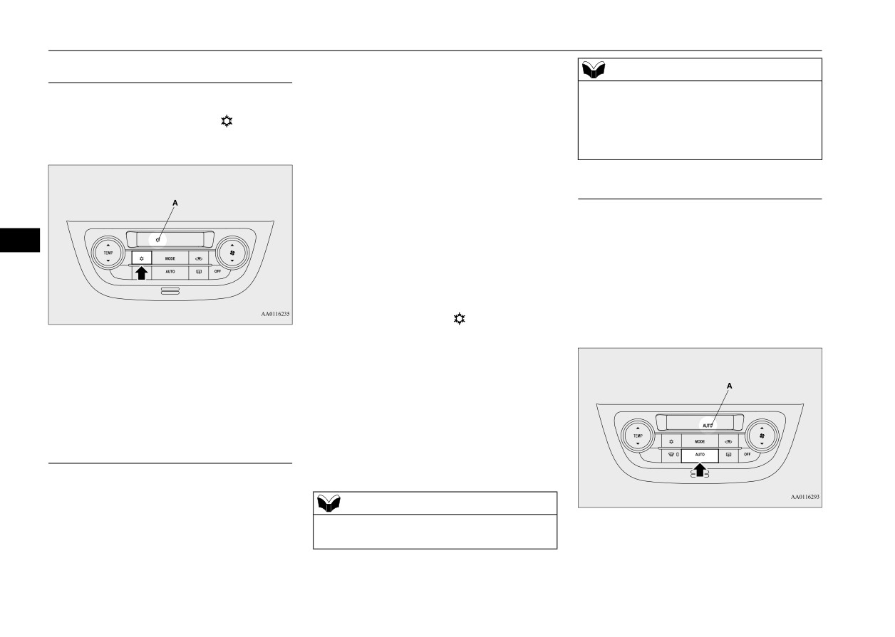
Air selection switch
N00737200368
The above indicates the factory settings. You
can personalize the air selection switch and
Normally, use the outside air position to keep
air conditioning switch to match your per-
the windshield and side windows clear and to
Defogger switch
sonal preferences.
quickly remove fog or frost from the wind-
N00703400015
Contact your Mitsubishi Motors dealer or a
shield.
When this switch is
pressed,
the mode
repair facility of your choice for assistance.
changes to the “
” mode. The indicator
To change the air selection, simply press the
Refer to “Personalizing the air conditioning
light (A) will come on. The selected mode is
air selection switch.
switch (Changing the function setting)” on
7-6
Comfort controls

Automatic air conditioning
The selected position will be shown in the
When the setting has changed, the system
CAUTION
display (A).
will beep and the
“
” indicator will
z Using recirculated air for a long time may
flash.
cause the windows to fog up.
z
Outside air: “
” indicator is ON
• When the setting has changed from
Outside air is introduced into the passen-
enabled to disabled,
ger compartment.
the system will beep three times and the
NOTE
z
Recirculated air: “
” indicator is ON
indicator will flash three times.
z If you press the AUTO switch to select auto-
Air is recirculated inside the passenger
• When the setting has changed from dis-
matic control after manual operation, the air
compartment.
abled to enabled,
selection switch will also be automatically
controlled.
the system will beep two times and the
indicator will flash three times.
7
Personalizing the air selection
NOTE
(Changing the function setting)
z
The factory setting is “Enable automatic air
N00760000089
control”.
You can change the following functions to
z
When the defogger switch is pressed, the air
selection will automatically change to the
match your preference.
outside air position, even if the system is set
to “Disable automatic air control”, in order
z Enable automatic air control:
to prevent windows from fogging up.
When the AUTO switch is pressed, the air
selection switch will also be automatically
When the air conditioning turns on, the air
controlled.
selection is controlled automatically. When
the air conditioning turns off, the air selection
z Disable automatic air control:
automatically goes back to the outside air
Even when the AUTO switch is pressed,
position.
the air selection switch will not be auto-
If high cooling performance is desired, or if
matically controlled.
the outside air is dusty or contaminated in
some way, use the recirculation position.
z Changing the settings
Switch to the outside air position every now
Press the air selection switch for about 10
and then to keep the windows from fogging
seconds or longer.
up.
Comfort controls
7-7
Automatic air conditioning
When the AUTO switch is pressed, or
Air conditioning switch
NOTE
when the temperature control switch has
N00737301409
z When the defogger switch is pressed, the air
been set to the minimum temperature, the
Push the switch, and the air conditioning
conditioning will run automatically, even if
air conditioning switch is automatically
compressor will turn on. The “
” indicator
the system is set to “Disable automatic air
controlled.
conditioning control”, in order to prevent
will be shown in the display (A).
windows from fogging up.
z
Disable automatic air conditioning con-
trol:
The air conditioning switch is not auto-
AUTO switch
matically controlled, unless the air condi-
N00703500016
tioning switch is used.
When the AUTO switch is pressed, the mode
selection, blower speed adjustment, recircu-
7
z
Changing the settings
lated/outside air selection, temperature
Press the air conditioning switch for about
adjustment, and air conditioner ON/OFF sta-
10 seconds or longer.
tus are all controlled automatically.
When the setting has changed, the system
The “AUTO” indicator will be shown in the
will beep and the
“
” indicator will
display (A).
flash.
Push the switch again and the air condition-
• When the setting has changed from
ing compressor will stop and the indicator
enabled to disabled,
goes off.
the system will beep three times and the
indicator will flash three times.
Personalizing the air conditioning
• When the setting has changed from dis-
switch (Changing the function set-
abled to enabled,
ting)
the system will beep two times and the
N00759800090
indicator will flash three times.
You can change the following functions to
match your preference.
NOTE
z The factory setting is “Enable automatic air
z Enable automatic air conditioning control:
conditioning control”.
7-8
Comfort controls
Automatic air conditioning
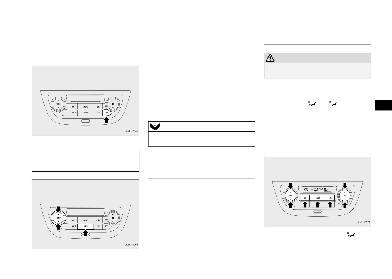
In normal conditions, use the system in the
OFF switch
Defrosting or defogging (wind-
AUTO mode and follow these procedures:
N00703600017
shield, door windows)
Push the switch to turn off the air condition-
1. Push the AUTO switch.
N00732401522
ing system.
2. Set the temperature control switch to the
CAUTION
desired temperature. The temperature can
z For safety, make sure you have a clear view
be set within a range of around 61 to 89
through all the windows.
(Type 1) or 17 to 31 (Type 2).
The vents, recirculation/outside air, blower
To remove frost or mist from the windshield
speed, temperature adjustment and ON/OFF
and door windows, use the MODE switch or
of air conditioning will be controlled auto-
defogger switch (“
” or “
”).
7
matically.
For ordinary defrosting
Use this setting to keep the windshield and
NOTE
door windows clear of mist, and to keep the
z Set the temperature at about 75 (Type 1) or
leg area heated
(when driving in rain or
24 (Type 2) under normal conditions.
snow).
Operating the air conditioning
Operating the air conditioning
system (automatic mode)
N00731701544
system (manual mode)
N00731801167
Blower speed and vent mode may be con-
trolled manually by setting the blower speed
selection switch and the MODE switch to the
desired positions. To return to automatic
operation, press the AUTO switch.
1. Set the MODE switch to the “
” posi-
tion.
Comfort controls
7-9
Important air conditioning operating tips
2. Set the air selection switch to the outside
3. When running the air conditioning, make
NOTE
air position.
sure the air intake, which is located in
z If the mode selection is set “
” position,
3. Select your desired blower speed by
front of the windshield, is free of obstruc-
you cannot turn the air conditioning off or
pressing the blower speed selection
tions such as leaves. Leaves collected in
select the recirculation position. This pre-
switch.
the air-intake chamber may reduce air
vents the windows from fogging up.
4. Select your desired temperature by press-
flow and plug the water drains.
z To defog quickly, direct the air flow from the
ing the temperature control switch.
side vents toward the door windows.
5. Push the air conditioning switch.
z When defrosting, do not set the temperature
Air conditioning system refrig-
to the maximum cool position. This will
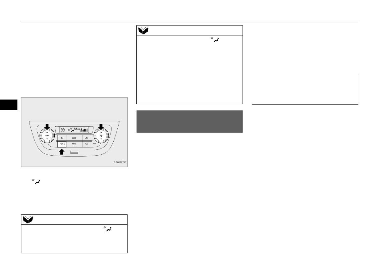
For quick defrosting
erant and lubricant recommen-
blow cool air on the window glass and fog it
up.
dations
7
If the air conditioning seems less effective
Important air conditioning
than usual, the cause might be a refrigerant
operating tips
leak.
N00733701434
Have the system inspected by your authorized
1. Park the vehicle in the shade whenever
Mitsubishi Motors dealer or a repair facility
possible. Parking in the hot sun makes the
of your choice.
vehicle interior extremely hot which then
requires more time to cool. If it is neces-
sary to park in the sun, open the windows
1. Push the defogger switch to change to the
for the first few minutes of air condition-
“
” position.
ing to expel the hot air.
2. Set your blower to the maximum speed.
2. Afterwards, keep the windows closed
3. Set the temperature to the highest posi-
when the air conditioning is in use. The
tion.
entry of outside air through open windows
will reduce cooling efficiency.
NOTE
z While the mode selection is set “
” posi-
tion, the air conditioning compressor will run
automatically. The outside air position will
also be selected automatically.
7-10
Comfort controls
Air purifier
The air filter’s ability to collect pollen and
CAUTION
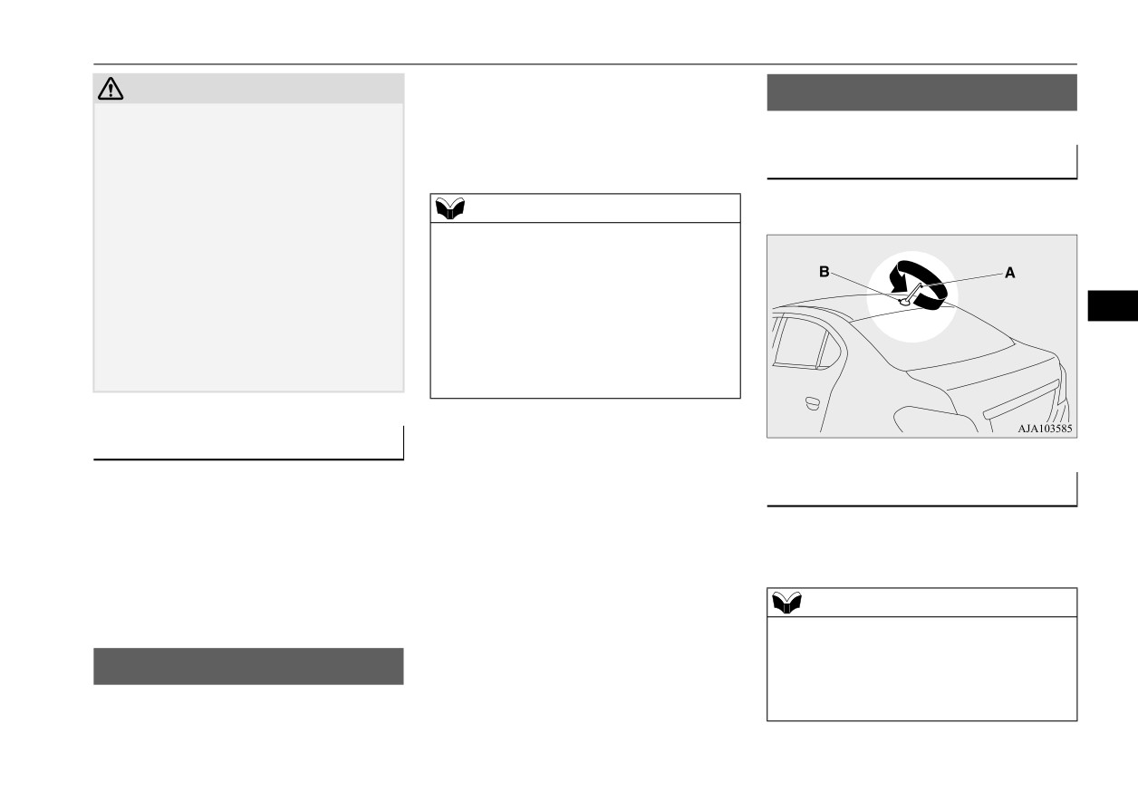
Antenna
dirt is reduced as it becomes dirty, so replace
z
The air conditioning system in your vehicle
N00734201553
it periodically. For the maintenance interval,
must be charged with the refrigerant HFO-
refer to the “WARRANTY AND MAINTE-
1234yf and the lubricant YR20.
NANCE MANUAL”.
To remove
Use of any other refrigerant or lubricant will
cause severe damage and may require replac-
Turn the pole (A) counterclockwise.
ing your vehicle’s entire air conditioning
NOTE
system.
z Operation in certain conditions such as driv-
The release of refrigerant into the atmo-
ing on a dusty road and frequent use of the
sphere is not recommended.
air conditioning can lead to reduction of ser-
The new refrigerant HFO-1234yf in your
vice life of the filter. When you feel that the
vehicle is designed not to harm the earth’s
air flow is lower than normal or when the
7
ozone layer. Additionally, it has a signifi-
windshield or windows start to fog up easily,
cantly reduced global warming impact on the
replace the air filter.
environment, compared to the refrigerant
Contact your Mitsubishi Motors dealer or a
HFC-134a.
repair facility of your choice for assistance.
During a long period of disuse
The air conditioning should be operated for at
To install
least five minutes each week, even in cold
weather. This includes the quick defrosting
Screw the pole (A) clockwise into the base
mode. Operating the air condition system
(B) until it is securely retained.
weekly maintains lubrication of the compres-
sor internal parts to keep the air conditioning
NOTE
in the best operating condition.
z Be sure to remove the roof antenna in the
following cases:
Air purifier
• When using an automatic car wash
N00733801246
• When covering your vehicle with a car
cover
The air conditioning system is equipped with
an air filter to remove pollen and dust.
Comfort controls
7-11

General information about your radio
NOTE
Signal transmission
Reflection
• When driving into a structure that has a low
ceiling
FM signals do not follow the earth surface
The reason why one can hear FM but not AM
nor are they reflected by the upper atmo-
in parking garages, under bridges etc., is that
sphere. For this reason, FM broadcasts cannot
FM signals, unlike AM signals, are reflected
General information about
be received over long distances. AM signals
by solid objects such as buildings, etc.
your radio
follow the earth’s surface and are reflected by
Because FM signals are easily reflected by
N00733901582
the upper atmosphere. For this reason, AM
buildings, this can also cause reception dis-
broadcasts can be received over longer dis-
turbances.
Your vehicle’s radio receives both AM and
tances.
The direct signal from the broadcast station
FM stations.
reaches the antenna slightly before the
The quality of your reception is affected by
7
reflected signal. This time difference may
distance, obstacles, and signal interference.
FM
AM
cause some reception disturbance or flutter.
This radio complies with Part 15 of Federal
This problem occurs primarily in urban areas.
Communications Commission (FCC) Rules.
Operation is subject to the following condi-
tions:
z The device may not cause harmful inter-
25 to 40 mile radius
100 mile radius
ference.
(40 to 64 km)
(160 km)
z This device must accept any interference
recieved, including interference that may
cause undesirable operation.
Weak reception (fading)
CAUTION
z Changes or modifications not expressly
Because of the limited range of FM signals
approved by the party meeting the above
and the way FM waves transmit, you may
conditions could void the user’s authority to
experience weak or fading FM reception.
operate the equipment.
When the broadcast is blocked by mountains
or similar obstructions, reception can be dis-
turbed.
7-12
Comfort controls

General information about your radio
Cross modulation
Causes of disturbances
If one listens to a weak station and is in the
FM reception is affected by the electrical sys-
vicinity of another strong station, both sta-
tems of vehicles in the vicinity, especially
tions might be received simultaneously.
those without an electronic noise suppression
device. The disturbance is even greater if the
station is weak or poorly tuned.
FM reception is not as sensitive to electrical
disturbances as AM. AM reception is sensi-
tive to electrical disturbances such as power
lines, lightning and other types of similar
7
electrical phenomena.
FM stereo reception
Stereo reception requires a high quality
broadcast signal. This means that types of
disturbances mentioned previously become
more marked and the reception range is
somewhat diminished during stereo recep-
tion.
Comfort controls
7-13
For emergencies
If the vehicle breaks down
8-2
If the operation mode cannot be changed to OFF
(vehicles equipped with the F.A.S.T.-key)
8-2
Jump-starting the engine
8-2
Engine overheating
8-4
Jack and tools
8-5
How to change a tire
8-6
Towing
8-12
8
Operation under adverse driving conditions
8-13
Fuel Pump Shut-off System
8-15
If the vehicle breaks down
If the vehicle breaks down
If the operation mode can-
WARNING
N00836300233
z To reduce the risk of igniting flammable
not be changed to OFF
gas that may be emitted from the battery,
If your vehicle breaks down on the road,
(vehicles equipped with the
carefully read this section before jump-
move to the shoulder and turn on the hazard
starting the vehicle.
warning flashers. If there is no shoulder, or
F.A.S.T.-key)
z Do not try to start your vehicle by pushing
the shoulder is not safe, drive in the right lane
N00860700117
or towing. This can cause an accident
slowly with the hazard lights flashing until
If the operation mode cannot be changed to
resulting in serious injury or death and
you come to a safe stopping place. Keep the
OFF, perform the following procedure.
can damage the vehicle.
flashers flashing.
1. Move the selector lever to the
“P”
(PARK) position, and then change the
NOTE
If the engine stops/fails
operation mode to OFF.
(For vehicles
z Do not use jumper cables if they have dam-
8
with continuously variable transmission
age or corrosion.
If the engine stops, there will be no power
(CVT))
assist to the steering and brakes, making these
2. One of the other causes could be low bat-
1. Take off any metal jewelry such as watch
difficult to use.
tery voltage. If this occurs, the keyless
bands or bracelets that might create an
entry system and the F.A.S.T.-key opera-
z The brake booster will not work, so the
accidental electrical contact.
tion will also not operate. Contact an
brakes will not grip well. The brake pedal
2. Position the vehicles close enough
authorized Mitsubishi Motors dealer.
will be harder to press than usual.
together so that the jumper cables can
z Since there is no power steering assist, the
reach, but be sure the vehicles aren’t
steering wheel will be hard to turn.
Jump-starting the engine
touching each other.
N00836401837
CAUTION
When the engine fails at the
If the engine cannot be started because the
z Check the other vehicle. It must have a 12-
battery is weak or dead, you can start it with
intersection
volt battery. If the other system isn’t 12-volt,
the battery from another vehicle using jumper
both systems can be damaged.
cables.
Get help from your passengers, bystanders,
etc. to push the vehicle and move it to a safe
area.
8-2
For emergencies

Jump-starting the engine
3. You could be injured if the vehicles move.
7. Connect one end of the other jumper cable
Set the parking brake firmly on each vehi-
to the negative
(-) terminal of the
cle. Put an automatic transaxle or CVT in
booster battery (B), and then connect the
“P” (PARK) or a manual transaxle in “N”
other end
to the designated ground
(Neutral).
location of the vehicle with the discharged
4. Turn the ignition switch to the
“OFF”
battery (A) at the point farthest from the
position or put the operation mode in
battery.
OFF.
WARNING
NOTE
z
Be sure to follow the proper order when
z Turn off all lights, heater, and other electrical
connecting
the
batteries,
of:
loads. This will avoid sparks and help save
both batteries.
WARNING
z
Make sure that the jumper cables and
z
Make sure that the connection
is made
8
your clothing are clear of the cooling fans
to the correct designated location
(as
5. Make sure your battery electrolyte is at
and drive belts. Entanglement with the
shown in the illustration) properly. If the
the proper level. (Refer to “Battery” on
fans or belts can cause serious personal
connection is directly made to the negative
page 9-11.)
(-) terminal of the battery, the flammable
injury.
gases from inside the battery might catch
WARNING
fire and explode, causing personal injury.
z If the electrolyte fluid is not visible, or
z
When connecting the jumper cable, do not
NOTE
looks frozen, DO NOT ATTEMPT JUMP
connect the positive (+) cable to the nega-
z
Open the terminal cover before connecting
STARTING!!
tive (-) terminal. Sparks can make the bat-
the jumper cable to the positive terminal of
The battery might split open or explode if
tery explode.
the battery.
the temperature is below the freezing
(Refer to “Battery: Disconnection and con-
point or if it is not filled to the proper
nection” on page 9-11.)
8. Start the engine in the vehicle providing
level.
z
Use the proper cables suitable for the battery
the boost. Let the engine idle a few min-
size.
utes, then start the engine in the vehicle
6. Connect one end of one jumper cable
Otherwise heat damage to the cables could
with the discharged battery.
to the positive
(+) terminal of the dis-
result.
9. After the engine is started, disconnect the
charged battery (A), and then connect the
cables in the reverse order from the way
other end
to the positive (+) terminal
you connected them.
of the booster battery (B).
For emergencies
8-3
Engine overheating
Charging the battery by using
As your vehicle has anti-lock
WARNING
an external battery charger
brakes
z To avoid personal injury, keep hands, hair,
jewelry and clothes away from the cooling
fan. The cooling fan can start at any time.
If you drive your vehicle with a low battery
WARNING
charge after the engine has been started by
z
Always remove the battery from your
4. If you see steam or spray coming from
using jumper cables, the engine may misfire.
vehicle when the battery is charged by an
under the hood, turn off the engine.
This can cause the anti-lock braking system
external battery charger.
5. If you do not see steam or spray coming
warning light to blink on and off. This is only
z
Keep sparks, cigarettes, and flames away
from under the hood, leave the engine on
due to the low battery voltage. It is not a
from the battery because the battery could
until the high coolant temperature warn-
problem with the brake system. If this hap-
explode.
ing light goes off. After the high coolant
pens, fully charge the battery and ensure the
z
Keep your work area well vented when
temperature warning light has gone off,
charging or using the battery in an
charging system is operating properly.
8
you can start driving again. If the high
enclosed space.
coolant temperature warning light stays
z
Remove all the caps before charging the
Engine overheating
on, turn off the engine.
battery.
N00836501418
z
Electrolyte (battery acid) is made of corro-
WARNING
sive diluted sulfuric acid. If electrolyte
If the high coolant temperature warning light
comes in contact with your hands, eyes,
illuminates while the engine is running, the
z Before raising the engine hood, check to
clothes, or the painted surface of your
see if there is steam or spray coming from
engine may be overheating. If this happens:
vehicle, thoroughly flush with water. If
under the hood. Steam or spray coming
electrolyte gets in your eyes, flush them
1. Stop the vehicle in a safe place. Turn on
from an overheated engine could seriously
immediately and thoroughly with water,
scald you.
the hazard warning flashers.
and get prompt medical attention.
Do not open the hood until there is no
2. With the engine still running, carefully
z
Always wear protective clothing and gog-
steam or spray.
raise the engine hood to vent the engine
gles when working near the battery.
compartment.
z
Keep the battery out of the reach of chil-
6. When you do not see any more steam or
3. Check that the cooling fan is running. If
dren.
the fan is not turning, stop the engine
spray, open the hood. Look for obvious
immediately and contact an authorized
leaks, such as a split radiator hose. Be
Mitsubishi Motors dealer or a repair facil-
careful as components will be hot. Any
ity of your choice for assistance.
leak source must be repaired.
8-4
For emergencies