Mitsubishi Mirage G4 (2022 year). Manual in english - page 7
Rear-view camera
NOTE
NOTE
General information
z Do not use an aerosol puncture-repair spray
z Tire inflation pressures vary with the ambi-
N00533001275
on any tire.
ent temperature. If the vehicle is subjected to
Your TPMS operates on a radio frequency
Such a spray could damage the tire inflation
large variations in ambient temperature, the
subject to Federal Communications Commis-
pressure sensors.
tire inflation pressures may be under-inflated
sion (FCC) Rules. This device complies with
Have any puncture repaired by an authorized
(causing the warning light come on) when
part 15 of FCC Rules.
Mitsubishi Motors dealer.
the ambient temperature is relatively low. If
Operation is subject to the following two con-
the warning light comes on, adjust the tire
5
ditions.
The TPMS may not work normally in the fol-
inflation pressure.
lowing circumstances:
z This device may not cause harmful inter-
z
A wireless facility or device using the
ference.
Whenever the tires and wheels
same frequency is near the vehicle.
z This device must accept any interference
z
Snow or ice is stuck inside the fenders
are replaced with new ones
received, including interference that may
and/or on the wheels.
N00532901235
cause undesired operation.
z
The tire inflation pressure sensor’s battery
If new wheels with new tire inflation pressure
is dead.
sensors are installed, their ID codes must be
WARNING
z
Wheels other than Mitsubishi Motors
programmed into the TPMS. Have tire and
z Changes or modifications not expressly
Genuine wheels are being used.
wheel replacement performed by an autho-
approved by the manufacturer for compli-
z
Wheels that are not fitted with tire infla-
rized Mitsubishi Motors dealer to avoid the
ance could void the user’s authority to
tion pressure sensors are being used.
risk of damaging the tire inflation pressure
operate the equipment.
z
Wheels whose ID codes are not memo-
sensors. If the wheel replacement is not done
rized by the vehicle are used.
by an authorized Mitsubishi Motors dealer, it
z
Compact spare tire is fitted on a road
is not covered by your warranty.
Rear-view camera
wheel.
N00546201444
z
A window tint that affects the radio wave
CAUTION
When the gearshift lever or the selector lever
signals is installed.
z The use of non-genuine wheels will prevent
is in the “R” position with the ignition switch
the proper fit of the tire inflation pressure
or the operation mode is in ON, the rear-view
sensors, resulting air leakage or damage of
image will be displayed on the screen of the
the sensors.
DISPLAY AUDIO or the Smartphone-link
Display Audio (SDA).
5-74
Features and controls
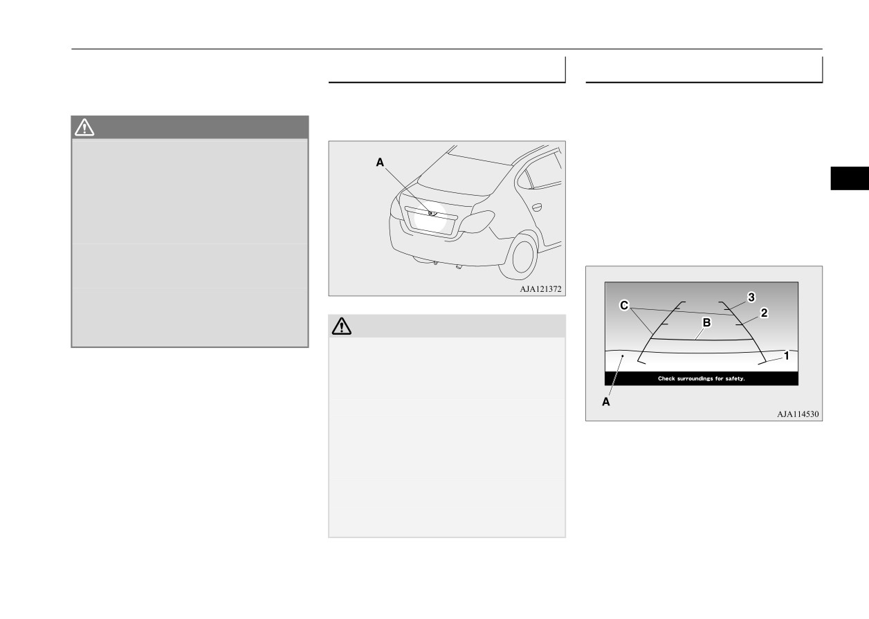
Rear-view camera
When the gearshift lever or the selector lever
Location of rear-view camera
Reference lines on the screen
is shifted out of the “R” position, the rear-
view image will go off.
The rear-view camera (A) is built-in to the
Reference lines and upper surface of the rear
trunk lid.
bumper (A) are displayed on the screen.
WARNING
z
The red line (B) indicates approximately
z
Never rely solely on the rear-view camera
to clear the area behind your vehicle.
20 inches (50 cm) behind the rear bumper.
Always check visually behind and all
z
The Green lines
(C) indicate approxi-
5
around your vehicle for persons, animals,
mately 8 inches (20 cm) outside of the
obstructions or other vehicles. Failure to
vehicle body.
do so can result in vehicle damage, serious
z
Short transverse lines (1 to 3) indicate dis-
injury or death.
tance from the rear bumper.
z
The rear-view camera is an aid system for
backing up, but it is not a substitute for
your visual confirmation.
z
The view on the screen is limited, and
objects outside the view, such as under the
bumper or around either corner of the
CAUTION
bumper, cannot be seen on the screen.
z
If the camera lens gets dirty, a clear image
cannot be obtained. As necessary, rinse the
lens with clean water and gently wipe with a
clean, soft cloth.
z
To avoid damaging the camera;
• Do not rub the cover excessively or polish
it by using an abrasive compound.
1:
Approximately at the rear edge of the
• Do not disassemble the camera.
rear bumper
• Do not splash hot water directly on the lens.
2:
Approximately 39 inches (100 cm)
• Do not spray the camera and its surround-
3:
Approximately 79 inches (200 cm)
ings with high-pressure water.
• Make sure that the trunk lid is securely
closed when backing up.
Features and controls
5-75

Rear-view camera
CAUTION
Case 2
z
The rear-view camera uses a wide-angle
lens. As a result, images and distances shown
on the screen are not exact.
z
Actual distance may be different from dis-
tance indicated by the lines on the screen,
depending on the loading condition of the
vehicle and road surface condition.
5
The reference lines for distance and vehicle
A- Actual objects
width are based on a level, flat road surface.
B- Objects shown on the screen
In the following cases, objects shown on the
screen will appear to be farther off than they
actually are.
CAUTION
NOTE
• When the rear of the vehicle is weighed
z
The reference lines for distance and vehicle
z
Mirror image is displayed on the screen.
down with the weight of passengers and
width are intended to indicate the distance to
z
Under certain circumstances, it may become
luggage in the vehicle. (Case 1)
a flat object such as a level, flat road surface.
difficult to see an image on the screen, even
• When there is an upward slope at the back.
They may not indicate correct distance
when the system is functioning correctly.
(Case 2)
depending on the shape of an obstacle.
• In a dark area, such as at night.
For example, when there is an object behind
• When water drops or condensation are on
the vehicle that has upper sections projecting
the lens.
Case 1
in the direction of the vehicle, the reference
• When sun light or headlights shine directly
lines on the screen will indicate that point A
into the lens.
is the farthest point and point B is the closest
point to the vehicle. In reality, point A and B
are actually the same distance from the vehi-
cle, and point C is farther off than point A
and B.
A- Actual objects
B- Objects shown on the screen
5-76
Features and controls

Instrument cluster
Instrument cluster
Type A
CAUTION
N00519001428
z The red zone indicates an engine speed
beyond the range of safe operation.
Select the correct shift position
(manual
transaxle) or selector position (CVT) to con-
trol the engine speed so that the tachometer
indicator does not enter the red zone.
5
Type B
1- Tachometer P.5-77
2- Multi-information display P.5-77
3- Speedometer P.5-77
4- Multi-information display switch
Multi-information display
N00555001507
Speedometer
The multi-information display includes the
N00519101344
odometer, trip odometer, service reminder,
The speedometer shows the vehicle speed in
fuel remaining, selector lever position, aver-
miles per hour (mph) or kilometers per hour
age fuel consumption, driving range, etc.
(km/h).
Tachometer
N00519201332
The tachometer shows engine revolutions per
minute. This allows the driver to determine
the most efficient selector position and engine
speed combinations.
This gauge also assists in evaluating engine
performance.
Features and controls
5-77

Multi-information display
5
1- Information display P.5-79
2- Frozen road warning P.5-82
3- Fuel remaining display P.5-82
4- Selector lever position display
(if so
equipped) P.5-45
NOTE
z When the ignition switch or the operation
mode is in OFF, the selector lever position
display, fuel remaining display and frozen
road warning are not displayed.
5-78
Features and controls
Multi-information display
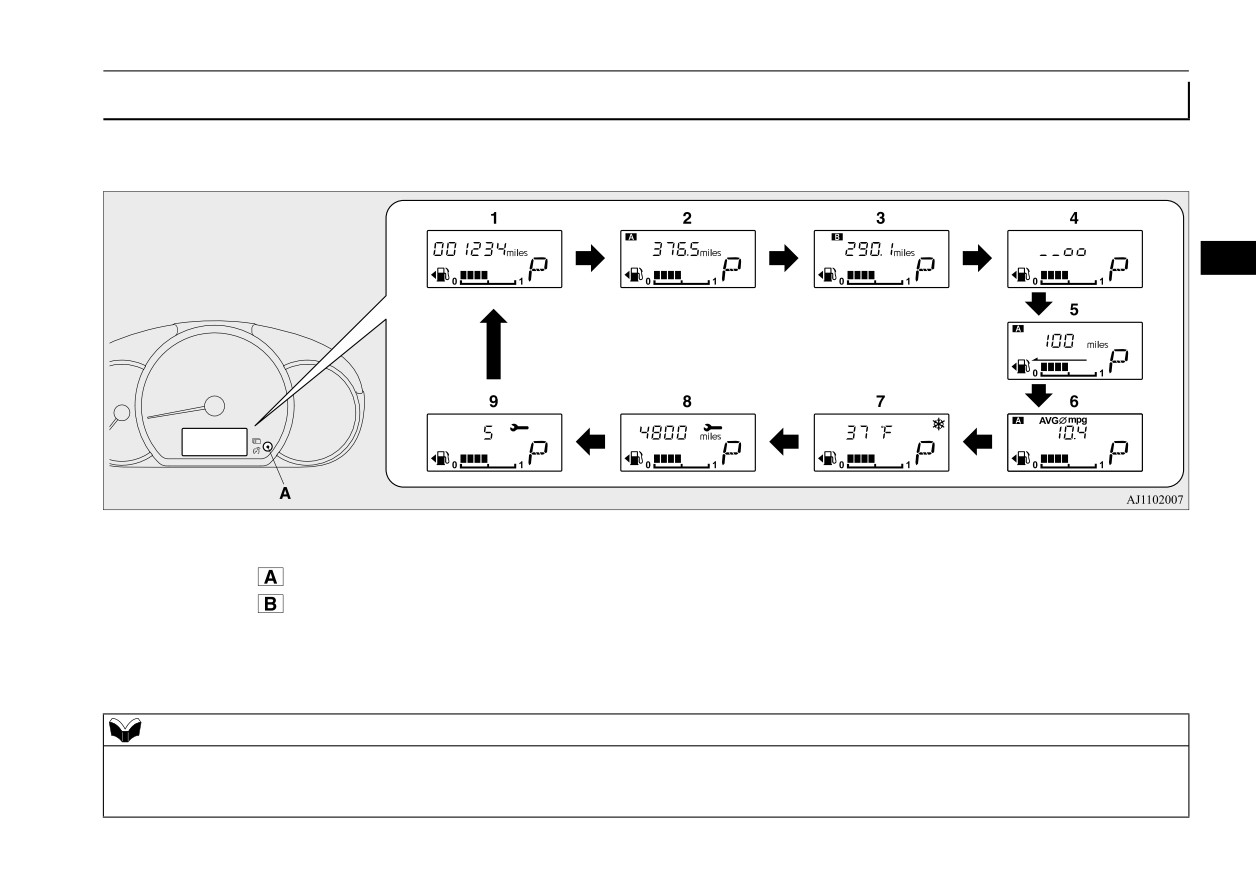
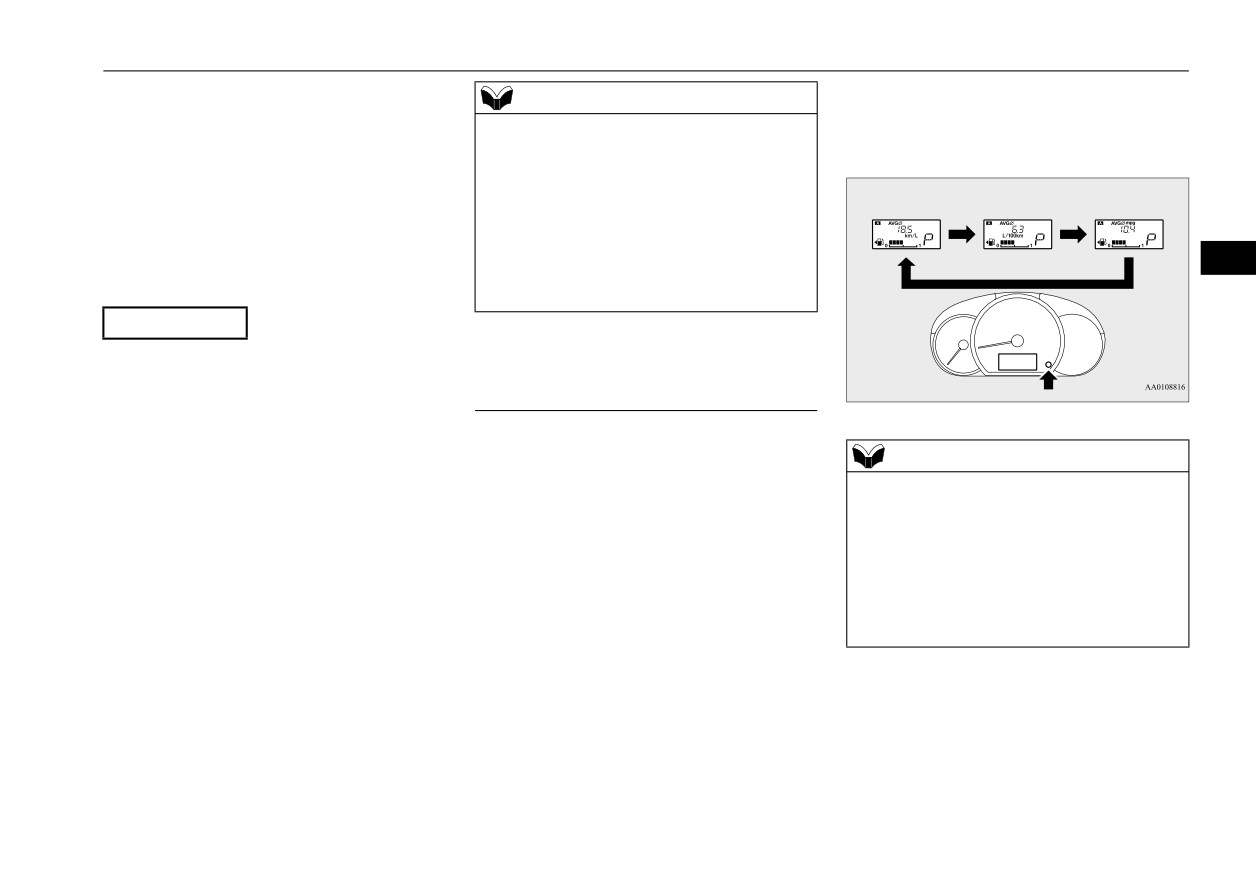
Information display
N00574801096
Each time you lightly press the multi-information display switch (A), the display switches in the following order.
5
1- Odometer P.5-80
5- Driving range display P.5-81
6- Average fuel consumption display
2- Trip odometer
P.5-80
P.5-81
3- Trip odometer
P.5-80
7- Outside temperature display P.5-81
4- Instrument panel light dimmer control
8- Service reminder (distance) P.5-83
P.5-80
9- Service reminder (month) P.5-83
NOTE
z When the ignition switch or the operation mode is in OFF, the driving range display, average fuel consumption display and outside temperature display are
not displayed.
z While driving, the service reminder is not displayed even if you operate the multi-information display switch.
Features and controls
5-79
Multi-information display
NOTE
z When the parking lights are not illuminated, the instrument panel light dimmer control is not displayed even if you operate the multi-information display
switch.
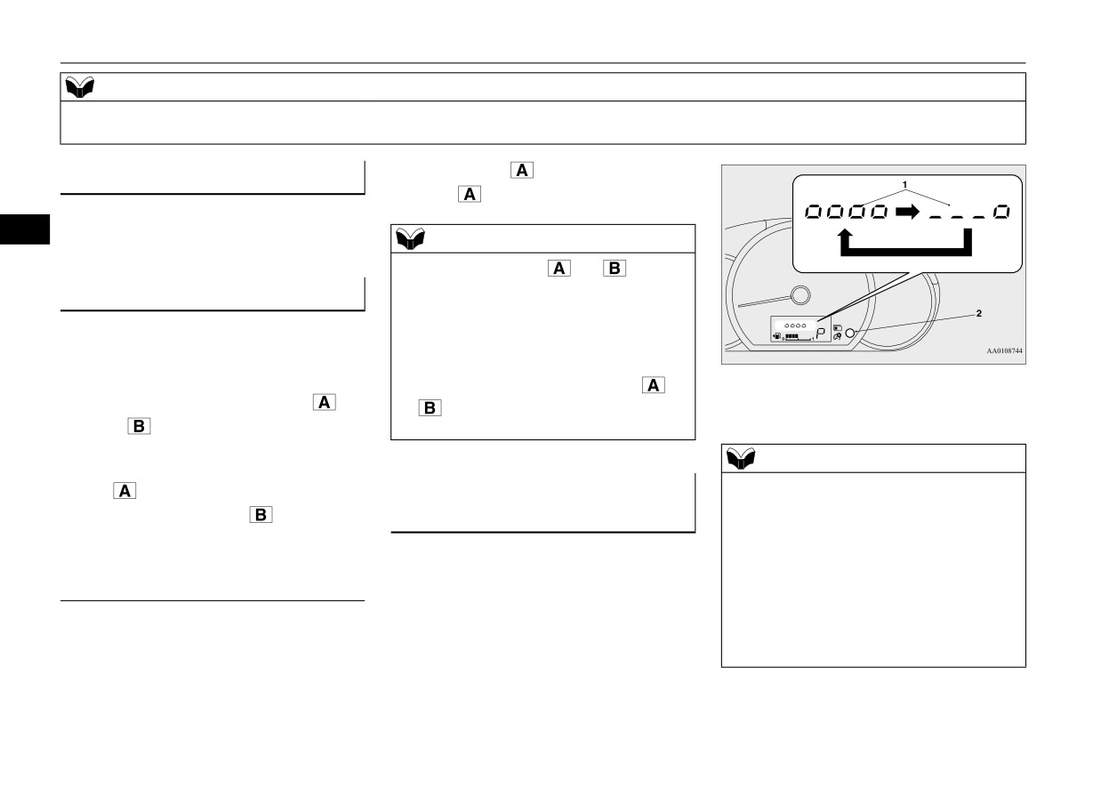
If trip odometer
is displayed, only trip
Odometer
Bright
Dim
N00574900016
odometer
will be reset.
The odometer indicates the total distance the
5
vehicle has traveled.
NOTE
z Both trip odometers
and
can count
up to 9999.9 miles/kilometers.
Trip odometer
When a trip odometer goes past
9999.9
N00575000014
miles/kilometers, it returns to 0.0 miles/kilo-
The trip odometer indicates the distance trav-
meters.
eled between two points.
z When disconnecting the battery terminal, the
memories of trip odometer displays
and
1-
Brightness level
Usage examples for trip odometer
, trip
2-
Multi-information display switch
are cleared, and their displays return to
odometer
“0.0 miles/kilometers”.
It is possible to measure two currently trav-
NOTE
eled distances, from home using trip odom-
z
When the parking lights are illuminated, you
eter
and from a particular point on the
Instrument panel light dimmer
can adjust to 8 levels.
way using trip odometer
control
z
Each time you reduce two brightness levels,
N00575101041
the segment display of the brightness level
Turn the parking lights on and press the
decreases by one segment.
z
If you press and hold the switch for longer
multi-information display switch (2), there is
To reset the trip odometer
than about 1 second, the brightness automati-
a sound and the brightness changes.
cally scrolls through its different levels, and
To return the display to 0, hold down the
stops scrolling when you release the switch.
multi-information display switch for about 1
Select your desired level of brightness.
second or more. Only the currently displayed
value will be reset.
Example
5-80
Features and controls
Multi-information display
NOTE
NOTE
NOTE
z The brightness level of the instruments is
z When your vehicle is stopped on an
z
The initial
(default) setting is
“Auto reset
stored when the ignition switch is turned to
extremely steep hill, the driving range value
mode”.
the “OFF” position or the operation mode is
may change. This is due to the movement of
z
Average fuel consumption may vary depend
put in OFF.
fuel in the tank and does not indicate any
on the driving conditions (road conditions,
On vehicles equipped with the automatic
breakdown.
how you drive, etc.).
light control, the instrument panel light dim-
z The display setting can be changed to the
The actual fuel consumption may differ from
mer control display is not displayed when it
preferred units (miles or km).
the fuel consumption displayed, so treat the
5
is bright outside the vehicle and the ignition
Refer to “Changing the function settings” on
fuel consumption displayed as just a rough
switch or the operation mode is ON.
page 5-84.
guideline.
z
Disconnecting the battery cable will erase
from memory the manual reset mode or auto
Driving range display
Average fuel consumption dis-
reset mode setting for the average fuel con-
N00575201042
play
sumption display.
This displays the approximate driving range
N00575300017
z
The display setting can be changed to the
(how many more miles or kilometers you can
preferred units {mpg, km/L, L/100 km}.
This displays the average fuel consumption
drive). When the driving range falls below
Refer to “Changing the function settings” on
from the last reset to the present.
approximately 30 miles (50 km), “---” is dis-
page 5-84.
The reset mode conditions for the average
played.
fuel consumption display can be switched
between “Auto reset” and “Manual reset”.
Outside temperature display
NOTE
For information on how to change the aver-
N00556501150
z The driving range is determined based on the
age fuel consumption display setting, refer to
Shows the temperature outside the vehicle.
fuel consumption data. This may vary
“Changing the function settings” on page
depending on the driving conditions and hab-
5-84.
its. Treat the distance displayed as just a
NOTE
rough guideline.
z The display setting can be changed to the
NOTE
preferred units (°F or °C).
z When you refuel, the driving range display is
updated.
z The average fuel consumption display can be
Refer to “Changing the function settings” on
However, if you only add a small amount of
reset separately in both auto reset mode and
page 5-84.
fuel, the correct value will not be displayed.
manual reset mode.
z Depending on factors such as the driving
Fill to a full tank whenever possible.
z “---” is displayed when the average fuel con-
conditions, the displayed temperature may
sumption cannot be measured.
vary from the actual outside temperature.
Features and controls
5-81

Multi-information display
turned to the “ON” position or the operation
Frozen road warning
mode is changed to ON.
N00579000067
When the remaining fuel level runs very low
If the outside air temperature drops below
(no segments displayed), the bar graph
approx. 37 °F (3 °C), the alarm sounds and
flashes.
the outside air temperature warning symbol
If the warning display appears, refuel imme-
(A) flashes for about 10 seconds.
diately.
5
1- Full
0- Empty
NOTE
z It may take several seconds to stabilize the
display after refilling the tank.
z If fuel is added with the ignition switch or
the operation mode in ON, the remaining
CAUTION
fuel display may incorrectly indicate the fuel
NOTE
z There is a danger the road might be icy, even
level.
z
On hills or curves, the display may be incor-
when this symbol is not flashing, so please
z The fuel lid mark (A) indicates that the fuel
rect due to the movement of fuel in the tank.
take care when driving.
tank filler door is located on the left side of
the vehicle. (Refer to “Filling the fuel tank”
on page 3-3.)
CAUTION
Fuel remaining display
z
Running out of gas could damage the cata-
N00575401057
lytic converter. If the warning display
Fuel remaining warning display
appears, refuel immediately.
The fuel remaining display indicates the fuel
level in the fuel tank when the ignition switch
When the remaining fuel level runs low (one
or the operation mode in ON.
segment is displayed), the last segment of the
fuel gauge flashes when the ignition switch is
5-82
Features and controls

Multi-information display
Service reminder
NOTE
To reset
N00556701312
z Shows the distance in units of 100 miles (100
Displays the approximate time until the next
km) and the time in units of 1 month.
The “---” display can be reset while the igni-
recommended periodic inspection.
“---” is
tion switch or the operation mode is in OFF.
displayed when the inspection time has
2. This informs you that a periodic inspec-
1. When you lightly press the multi-informa-
arrived.
tion is due. Contact an authorized
tion display switch a few times, the infor-
Mitsubishi Motors dealer or a repair facil-
mation display switches to the service
5
ity of your choice to have the system
NOTE
reminder display.
checked.
z The service reminder time can be modified
3. After your vehicle is inspected at an
by an authorized Mitsubishi Motors dealer,
authorized Mitsubishi Motors dealer, it
to adjust for severe usage, etc. Refer to
“Severe maintenance schedule” in your vehi-
displays the time until the next periodic
cle’s Warranty and Maintenance Manual. For
inspection.
further information, please contact your
authorized Mitsubishi Motors dealer.
NOTE
z
When the next periodic inspection is
approaching, the wrench symbol will be dis-
Distance
played whenever the ignition switch is
turned from the “OFF” position to the “ON”
position or when the operation mode is
changed from OFF to ON.
The wrench symbol will continuously be dis-
2. Press and hold the multi-information dis-
Month
played, even on non-service reminder dis-
play switch for about 1 second or more to
plays (odometer, trip meter, etc.), until the
make the wrench symbol start flashing. (If
service reminder is reset.
there is no operation for about 10 seconds
When the service reminder resets, the
with flashing, the display will revert to its
wrench symbol will not be displayed until
original indication.)
the next periodic inspection.
1. Shows the time
until the
next
periodic
inspection.
Features and controls
5-83
Multi-information display
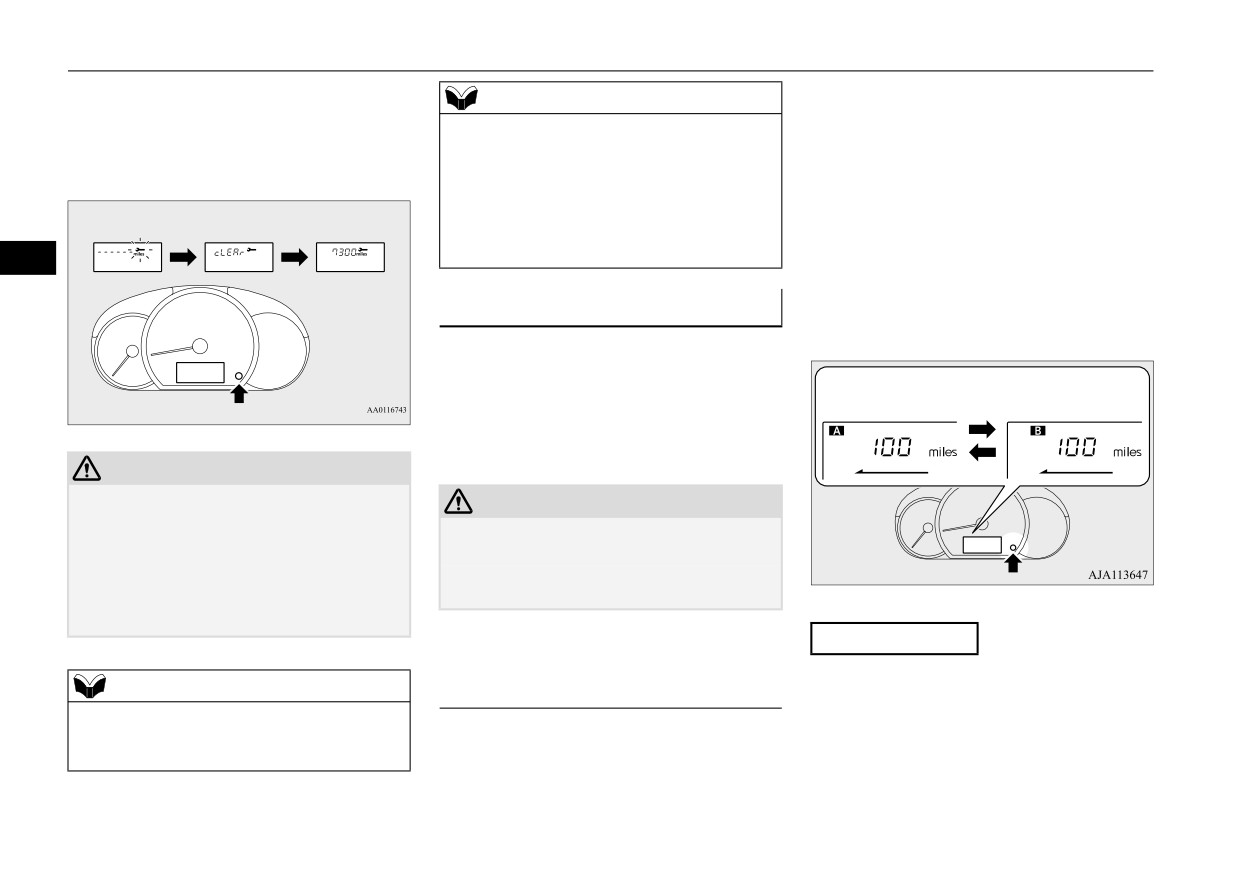
3. With this indicator flashing, if you lightly
1. When you lightly press the multi-informa-
NOTE
press the multi-information meter switch,
tion display switch a few times, the infor-
z When “---” is displayed, after a certain dis-
the display switches from
“---”
to
mation display switches to the driving
tance and a certain period of time, the dis-
“cLEAr”. After that, the time until
the
range display.
play is reset and the time until the next
next periodic inspection is shown.
Refer to “Information display” on page
periodic inspection is displayed.
5-79.
z If you accidentally reset the display, consult
2. Each time you press the multi-information
an authorized Mitsubishi Motors dealer for
assistance.
display switch for 1 second or more on
5
driving range display, you can switch
reset mode for average fuel consumption.
Changing the function settings
(A: Auto reset mode, B: Manual reset
N00556801267
mode)
The “Average fuel consumption reset mode”,
“Fuel consumption unit” and “Temperature
unit” setting can be modified as desired,
Auto reset mode
Manual reset mode
when the ignition switch or the operation
mode is ON.
CAUTION
z
The customer is responsible for making sure
CAUTION
that regular inspections and maintenance and
z The driver should not operate the display
periodic inspections and maintenance are
while the vehicle is in motion.
performed.
z When operating the system, stop the vehicle
Inspections and maintenance must be per-
in a safe area.
formed to prevent accidents and malfunc-
tions.
Manual reset mode
Changing the reset mode for aver-
z When the average
fuel consumption is
NOTE
age fuel consumption
being displayed, if you hold down the
z
The “---” display cannot be reset while the
N00575501032
multi-information display switch, these
ignition switch or the operation mode is in
You can change the mode condition for the
calculations will be reset to zero.
ON.
average fuel consumption display to “Auto
z When the following operation is per-
reset” or “Manual reset”.
formed, the mode setting changes auto-
matically from manual to auto.
5-84
Features and controls
Multi-information display
[Except for vehicles equipped with the
3. Press and hold the multi-information dis-
NOTE
F.A.S.T.-key]
play switch to switch in sequence from
z The average fuel consumption display can be
Turn the ignition switch to the “ON” posi-
“km/L”
“L/100
km”
“mpg”
reset separately for the auto reset mode and
tion from the “ACC” or “OFF” position.
“km/L”.
for the manual reset mode.
z Disconnecting the battery cable will erase
[For vehicles equipped with the F.A.S.T.-
from memory the manual reset mode or auto
key]
reset mode setting for the average fuel con-
Change the operation mode to ON from
sumption display.
ACC or OFF.
5
z The initial
(default) setting is
“Auto reset
mode”.
Auto reset mode
z
When the average fuel consumption is
Changing the fuel consumption
being displayed, if you hold down the
display unit
multi-information display switch, these
N00557100156
calculations will be reset to zero.
The fuel consumption display unit can be
z
When the engine switch or the operation
NOTE
changed. The distance and amount units are
mode is in the following conditions, the
also switched to match the selected fuel con-
z
The display units for the driving range, the
average fuel consumption display will
average fuel consumption are changed, but
sumption unit.
automatically reset.
the units for the indicating needle (speedom-
eter), the odometer, the trip odometer and the
1. When you lightly press the multi-informa-
[Except for vehicles equipped with the
service reminder will remain unchanged.
tion display switch a few times, the infor-
F.A.S.T.-key]
z
If the battery is disconnected, the memory of
mation display switches to the average
The ignition switch has been set to the
the unit setting is erased and it returns auto-
fuel consumption display.
“ACC” or “OFF” position for about 4
matically to factory setting.
Refer to “Information display” on page
hours or more.
5-79.
[For vehicles equipped with the F.A.S.T.-
2. Press and hold the multi-information dis-
The distance units is also changed in the fol-
key]
play switch for about 5 seconds or more
lowing combinations to match the selected
The operation mode has been set to ACC
until buzzer sound is heard twice.
fuel consumption unit.
or OFF for about 4 hours or more.
Features and controls
5-85
Multi-information display
Distance
Fuel consumption
(driving range)
km/L
km
L/100 km
km
mpg
mile (s)
5
Changing the temperature unit
N00557201268
The temperature display unit can be switched.
1. When you lightly press the multi-informa-
tion display switch a few times, the infor-
mation display switches to the outside
temperature display.
Refer to “Information display” on page
5-79.
2. Each time you press the multi-information
display switch for 5 seconds or more on
outside temperature display, you can
switch from °F to °C or from °C to °F unit
of outside temperature display.
NOTE
z The temperature value on air conditioning
panel is switched in conjunction with outside
temperature display unit of the multi-infor-
mation display.
However, “°F” or “°C” are not shown to tem-
perature display of an air conditioning.
5-86
Features and controls
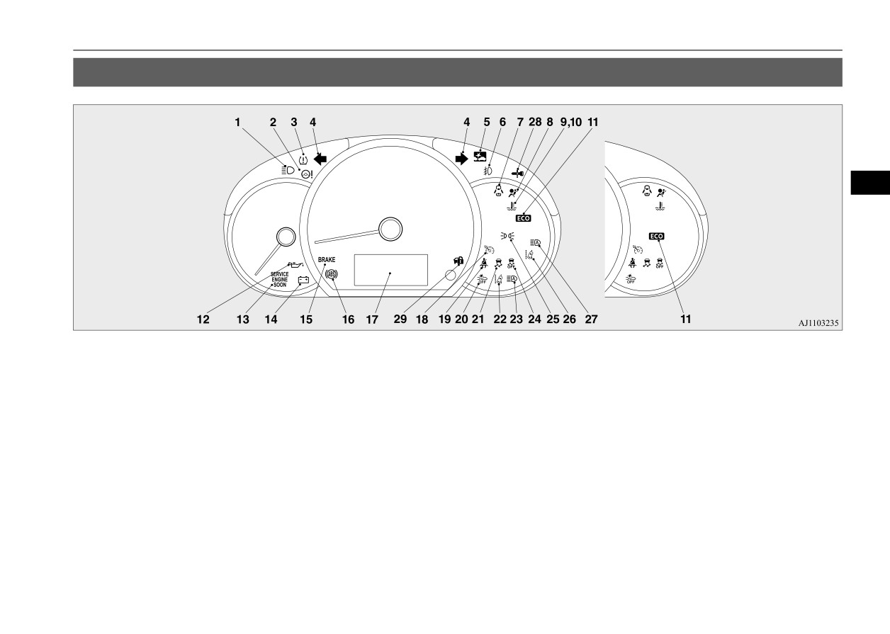
Indicator and warning light package
Indicator and warning light package
N00519801976
5
1- High beam indicator P.5-88
9- High coolant temperature warning light
18- Cruise control indicator
(if
so
2- Electric power steering system warning
(red) P.5-90
equipped) P.5-56
light P.5-52
10- Low coolant temperature indicator
19- Driver’s seat belt reminder/warning
3- Tire pressure monitoring system warn-
(green) P.5-88
light P.4-11
ing light P.5-72
11- ECO indicator P.5-88
20- Forward Collision Mitigation system
4- Turn signal indicators/Hazard warning
12- Oil pressure warning light P.5-90
(FCM) OFF indicator P.5-64
lights P.5-88
13- Engine malfunction indicator
(“SER-
21- Active stability control (ASC) indica-
5- Forward Collision Mitigation system
VICE ENGINE SOON”) P.5-89
tor/warning light P.5-55
(FCM) indicator P.5-66
14- Charging system warning light
22- Lane Departure Warning (LDW) light
6- Front fog light indicator
(if so
P.5-90
(yellow) (if so equipped) P.5-70
equipped) P.5-88
15- Brake warning light P.5-88
23- Automatic High Beam (AHB) warning
7- Door-ajar warning light P.5-90
16- Anti-lock braking system warning light
light (yellow) (if so equipped)
8- Supplemental Restraint System (SRS)
P.5-51
P.5-97
warning light P.4-31
17- Multi-information display P.5-77
Features and controls
5-87
Indicators
24- Active stability control
(ASC) OFF
High beam indicator
ECO indicator
indicator/warning light P.5-55
N00520100086
N00568800036
25- Position indicator
(if so equipped)
A blue light comes on when the headlights
This indicator comes on while fuel-efficient
P.5-88
are on high beam.
driving is achieved.
26- Lane Departure Warning (LDW) indi-
cator (green) (if so equipped) P.5-68
27- Automatic High Beam (AHB) indicator
Front fog light indicator (if so
Warning lights
(green) (if so equipped) P.5-95
5
equipped)
N00520300147
28- For details, refer to “Warning activa-
N00520200175
tion” on page 5-15 (if so equipped)
Brake warning light and buzzer
29- For details, refer to “Warning activa-
This indicator comes on while the front fog
N00520400526
tion” on page 5-15 (if so equipped)
lights are on.
This light comes on when the ignition switch
is turned to the “ON” position (engine off) or
Indicators
Position indicator
(if so equipped)
the operation mode is put in ON.
N00519900127
N00551301049
When the engine is started, the light should
go off a few seconds later.
This indicator light illuminates while the
Turn signal indicators/Hazard
The warning light also illuminates after start-
parking lights are on.
warning lights
ing the engine under the following condi-
N00520000216
tions.
Low coolant temperature indi-
The arrows will flash in time with the corre-
z When the parking brake is still applied.
cator - green
sponding exterior turn signals when the turn
z When the brake fluid level is low.
signal lever is used.
N00575600010
z When the brake system circuit is not
This indicator comes on in green while the
working properly.
Both arrows will flash when the hazard warn-
coolant temperature is low.
ing flasher switch is pressed.
When the vehicle is moving at more than 5
NOTE
mph (8 km/h) and the parking brake applied,
NOTE
a buzzer will sound to inform the driver that
z When the indicator goes out, this should be
z If the indicator flashes faster than usual or if
used as a rough indication of when the heat-
the parking brake is not properly release.
the indicator stays on without flashing, check
ing starts working.
for a malfunctioning turn signal light bulb or
turn signal connection.
5-88
Features and controls
Warning lights
Before driving, be sure that the parking brake
Engine malfunction indicator
CAUTION
is fully released and the brake warning light
(“SERVICE ENGINE SOON”)
z
Driving for a long time with the engine mal-
is off.
function indicator on may cause more dam-
N00520501885
age to the emission control system. This
This indicator is a part of the onboard diag-
CAUTION
could also affect fuel economy and drivabil-
nostic
(OBD) system which monitors the
ity.
z
If the brake warning light and the Anti-lock
braking system warning light are illuminated
emissions, engine control system or continu-
z
If this indicator does not come on when the
at the same time, the braking force distribu-
ously variable transmission
(CVT) control
ignition switch is turned to the “ON” posi-
5
tion function will not operate, the vehicle
system. If a problem is detected in one of
tion or the operation mode is put in ON, have
may be destabilized during sudden braking
these systems, this indicator illuminates or
the system checked at an authorized
under the following conditions.
flashes. When the ignition switch is turned to
Mitsubishi Motors dealer or a repair facility
• When the brake warning light does not go
the “ON” position or the operation mode is
of your choice.
out even when the parking brake is
z
If the engine malfunction indicator comes on
put in ON, this indicator normally comes on
released.
while the engine is running, avoid driving at
and goes off after the engine has started.
• When the brake warning light stays on
high speeds.
while driving.
During vehicle operation with the indicator
This indicator will come on if the fuel tank
on, the vehicle may not accelerate when you
If the above occurs, avoid sudden braking
filler cap is not properly tightened. If this
depress the accelerator pedal.
and high-speed driving. Park the vehicle in a
indicator comes on and stays on after refuel-
When the vehicle is stationary with the indi-
safe place, and contact an authorized
ing, stop the engine and check that the cap is
cator on, you must depress the brake pedal
Mitsubishi Motors dealer or a repair facility
properly tightened. (Turn the cap clockwise
more firmly than usual since the engine
of your choice as soon as possible.
until you hear clicking sounds.)
idling speed is higher than usual and a vehi-
z
The vehicle should be brought to a halt in the
If this indicator does not go off after several
cle with a CVT has a stronger tendency to
following manner when brake performance
seconds or lights up while driving, have the
creep forward.
is deteriorated.
system checked immediately at an authorized
• Confirm that the vehicle slows down when
you press down on the brake pedal harder
Mitsubishi Motors dealer or a repair facility
than usual. In some cases, the brake pedal
of your choice.
may go all the way to the floor.
• Should the brakes fail, use engine braking
to reduce your speed and slowly apply the
parking brake.
Depress the brake pedal to illuminate the
stop lights and to alert the vehicles behind
you.
Features and controls
5-89
Warning lights
NOTE
Oil pressure warning light
CAUTION
z Do not disconnect the battery cable when the
N00520700170
z
If the light comes on during vehicle opera-
engine malfunction indicator
(“SERVICE
tion, it indicates that the engine is possibly
This light comes on when the engine oil pres-
ENGINE SOON”) is on.
overheating. Continued driving could make
sure is below normal. If the light stays on
The engine electronic control module stores
the engine fail. Immediately stop the vehicle
while driving, stop the engine as soon as pos-
critical OBD information (especially exhaust
in a safe place and take appropriate action.
sible. Do not run the engine until the cause of
emission data), which may be lost if the bat-
(Refer to “Engine overheating” on page 8-4.)
the low oil pressure is corrected.
tery cable is disconnected while the engine
5
malfunction indicator is on. This will make it
difficult to diagnose the cause of future prob-
CAUTION
NOTE
lems.
z If this light comes on when the engine oil
z
The high coolant temperature warning light
level is not low, have your vehicle checked at
may illuminate when the vehicle has been
an authorized Mitsubishi Motors dealer or a
driven at high speeds or on hilly roads. This
Charging system warning light
repair facility of your choice.
illuminating does not necessarily indicate a
N00520601365
z This warning light does not show the amount
problem. It should stop if you keep the
of oil in the crankcase. This can only be
engine running for a while or continue driv-
This light comes on in the event of a malfunc-
determined by checking the oil level with the
ing the vehicle.
tion in the charging system or when the igni-
dipstick with the engine turned off.
tion switch is turned to the “ON” position
(engine off) or the operation mode is put in
Door-ajar warning light and
ON. When the engine is started, the light
High coolant temperature
should go out. Check to make sure that the
buzzer
light has gone out before driving.
warning light - red
N00520901342
N00575700011
This light comes on when any door is open or
This light comes on in red if the coolant tem-
not completely closed.
CAUTION
perature becomes excessively high.
When the vehicle is moving at more than 5
z If the warning light stays on while the engine
is running, park your vehicle in a safe place
mph (8 km/h) and any door is open or ajar, a
immediately and contact an authorized Mit-
tone will sound 4 times to inform the driver
subishi Motors dealer or a repair facility of
that any door is not properly shut.
your choice to have the system checked.
CAUTION
z Before driving, make sure that the door-ajar
warning light is off.
5-90
Features and controls

Combination headlights and dimmer switch
NOTE
Type 1
Vehicles equipped with daytime running
z When the auto cut-out function of the doom
lights
Rotate the switch to operate the lights.
light is been activated, the light goes out
[When the engine is started, and the parking
automatically after about 30 minutes.
Refer to “Dome light” on page 5-107.
brake is released]
The daytime running lights will be illumi-
nated:
Combination headlights and
5
dimmer switch
The daytime running lights illumi-
OFF
N00522502059
nated
The daytime running lights illumi-
Headlights
nated
Parking, tail, front and rear side-
marker lights, license plate and
The combinations of switch operations and
NOTE
instrument panel lights on
illuminated lights differ in accordance with
z
Do not leave the headlights and other lights
the following conditions.
Headlights and other lights on
on for a long period of time when the engine
is not running. The battery will run down.
Except for vehicles equipped with day-
z
When it rains, or when the vehicle has been
time running lights
NOTE
washed, the inside of the lens sometimes
becomes foggy. This is the same as when
z
Once the daytime running light come on,
OFF
All lights off
window glass mists up on a humid day, and
they do not go out until the ignition switch is
does not indicate a problem. When the light
turned to the “OFF” or “ACC” position or
Parking, tail, front and rear side-
is switched on, the heat will dry out the fog.
the operation mode is changed to OFF or
marker lights, license plate and
However, if water collects inside the light,
ACC.
instrument panel lights on
have it checked by an authorized Mitsubishi
Motors dealer or a repair facility of your
Headlights and other lights on
[When the engine is not running, or when the
choice.
engine is running but the parking brake is not
released]
Features and controls
5-91

Combination headlights and dimmer switch
The engine starts when the lights are off.
Except for vehicles equipped with day-
NOTE
time running lights
z Once the daytime running lights come on,
OFF
All lights off
they do not go out until the ignition switch is
Parking, tail, front and rear side-
Headlights and other lights turn on
turned to the “OFF” or “ACC” position or
marker lights, license plate and
AUTO
and off automatically in accor-
the operation mode is changed to OFF or
instrument panel lights on
dance with outside light level.
ACC.
Headlights and other lights on
Tail, front and rear side-marker-
5
lights, license plate and instrument
[When the engine is not running, or when the
panel lights on
engine is running but the parking brake is not
Type 2
released]
Headlights and other lights on
Rotate the switch to operate the lights.
The engine starts when the lights are off.
Vehicles equipped with daytime running
Headlights and other lights turn on
lights
AUTO
and off automatically in accor-
dance with outside light level.
[When the engine is started, and the parking
brake is released]
Parking, tail, front and rear side-
marker lights, license plate and
The daytime running lights illumi-
instrument panel lights on
nated (when it is light outside the
Headlights and other lights on
vehicle)
AUTO
Headlights and other lights turn on
and off automatically in accor-
The combinations of switch operations
and
dance with outside light level.
illuminated lights differ in accordance with
The daytime running lights illumi-
the following conditions.
nated
Tail, front and rear side-marker
lights, license plate and instrument
panel lights on
Headlights and other lights on
5-92
Features and controls
Combination headlights and dimmer switch
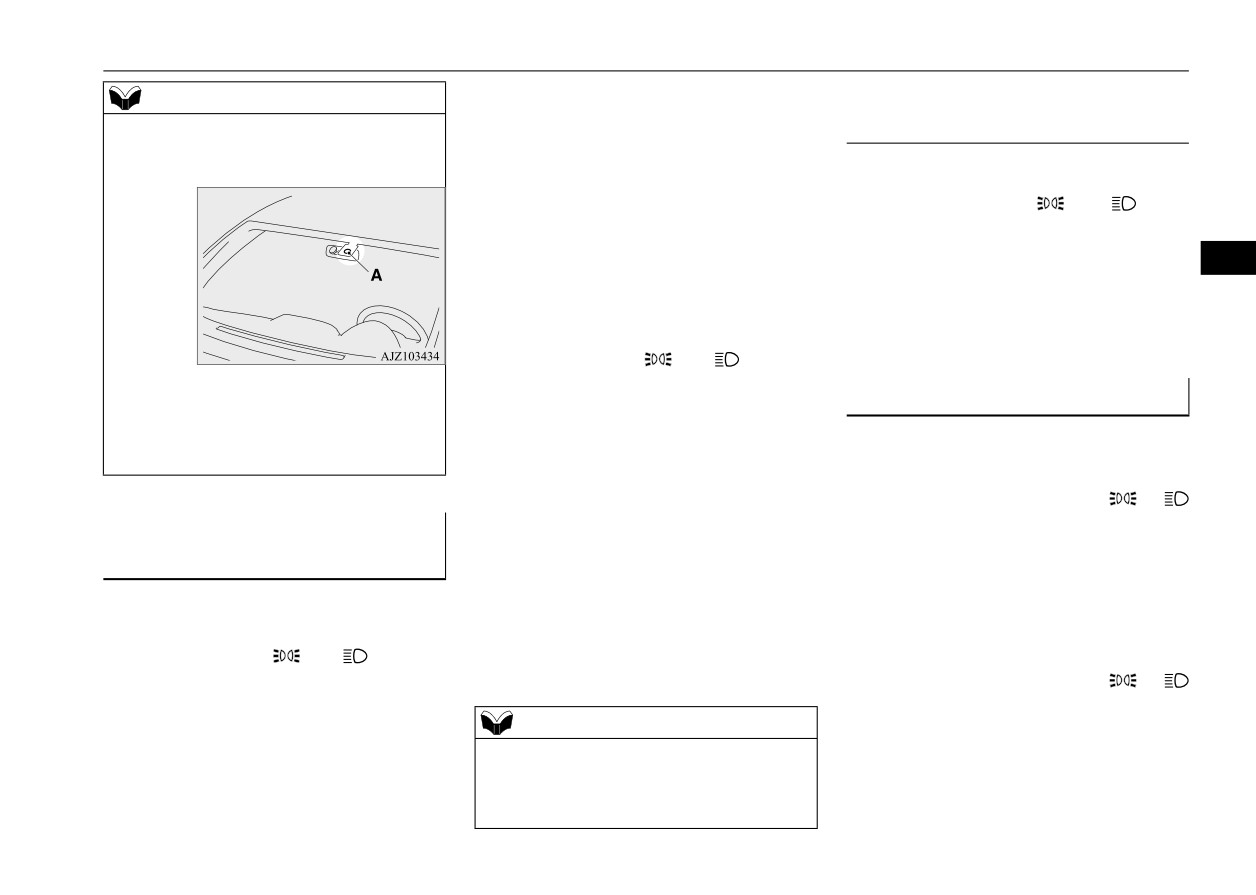
The ignition switch is turned to the “OFF”
NOTE
When you want to keep the lights
or “ACC” position or the key is removed
z
Do not cover the sensor (A) for the automatic
on:
from the ignition switch and the driver’s
on/off control by affixing a sticker or label to
door is opened.
the windshield.
If the combination headlights and dimmer
[For vehicles equipped with the F.A.S.T.-
switch is turned to the “
” or “
” posi-
key]
tion again after the engine is turned off, the
The operation mode is changed to OFF or
about
3-minute auto-cutout
function
ACC and the driver’s door is opened.
5
described above will not work. The lights (the
parking lights, tail lights and license plate
z
If the following operation is performed
lights) will stay on and will not turn off auto-
with the combination headlights and dim-
matically.
mer switch in the “
” or “
” position,
z
If the lights do not turn on or off with the
the lights automatically turn off after
switch in the
“AUTO” position, manually
Headlight reminder buzzer
about 3 minutes.
operate the switch. Have the system checked
N00549801308
by an authorized Mitsubishi Motors dealer or
[Except for vehicles equipped with the
[When using a key to start the engine]
a repair facility of your choice.
F.A.S.T.-key]
If the driver’s door is opened while the com-
The ignition switch is turned to the “OFF”
bination headlight switch is in the
or
or “ACC” position or the key is removed
position and the key is removed from the
Light auto-cutout function
from the ignition switch and the driver’s
ignition switch, the tone will sound to remind
(headlights and other lights)
door is not opened.
you to turn off the light.
N00532600570
[For vehicles equipped with the F.A.S.T.-
z If the following operation is performed
[When using the F.A.S.T.-key to start the
key]
with the combination headlights and dim-
engine]
The operation mode is changed to OFF or
mer switch in the “
” or “
” position,
If the driver’s door is opened while the com-
ACC and the driver’s door is not opened.
the lights automatically turn off.
bination headlight switch is in the
or
position and the operation mode is in OFF,
[Except for vehicles equipped with the
NOTE
the tone will sound to remind you to turn off
F.A.S.T.-key]
z The light auto-cutout function can be deacti-
the light.
vated.
See your authorized Mitsubishi Motors
In either case, the lights will turn off automat-
dealer for details.
ically and so will the tone. You can also turn
Features and controls
5-93
Combination headlights and dimmer switch
the light switch to the “OFF” or “AUTO”
Automatic High Beam (AHB) (if
position*, or close the driver’s door to stop
the tone.
so equipped)
N00591300103
*: Whether or not your vehicle is equipped
The Automatic High Beam (AHB) turns the
with “OFF” or “AUTO” position on the
high beam light on or off automatically
combination headlights and dimmer
according to surrounding light conditions.
switch depends on the vehicle specifica-
The sensor (A) detects
lights, such as the
5
tions.
lights of an oncoming
vehicle,
a
vehicle
ahead or street lights.
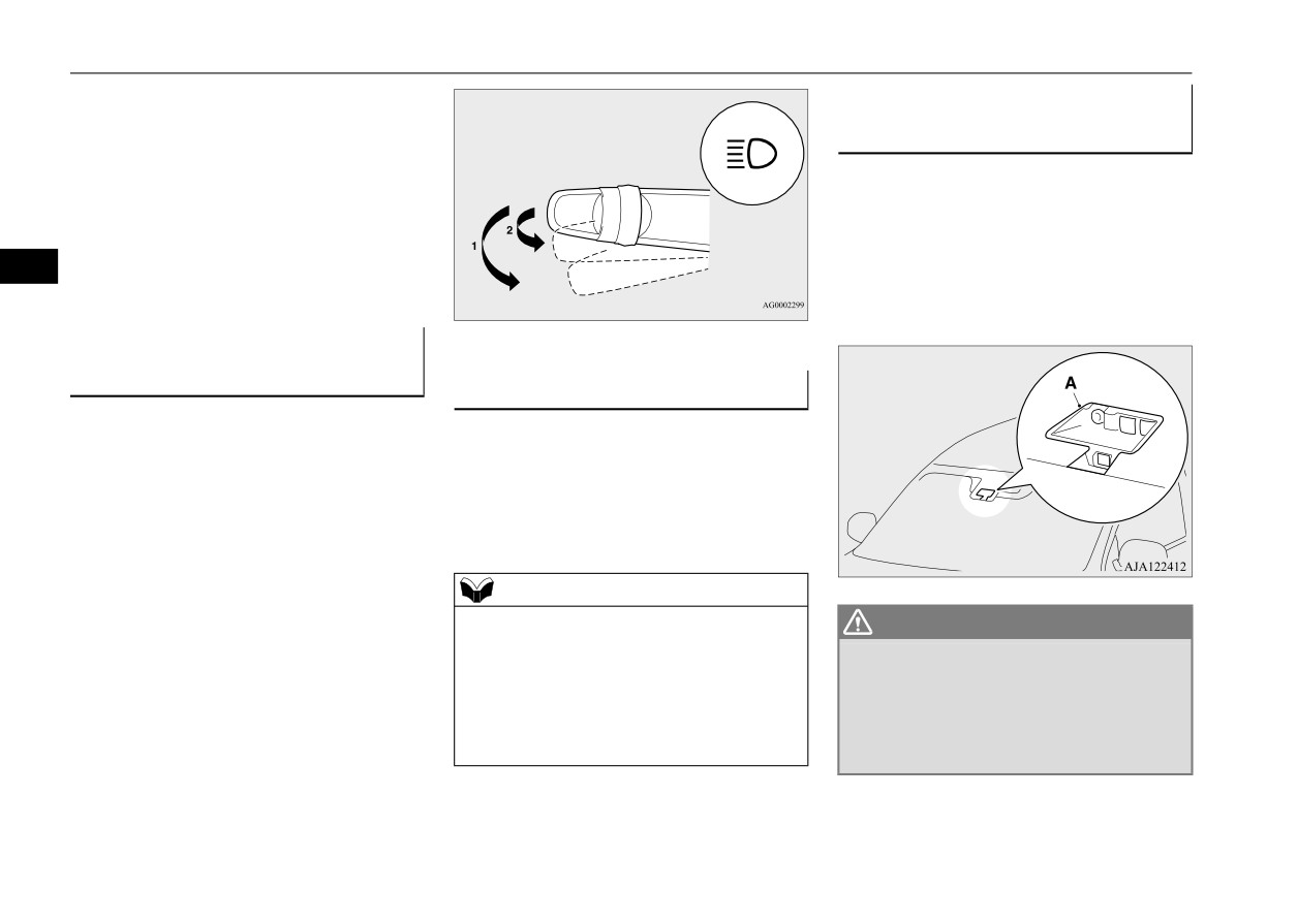
Dimmer (high/low beam
change)
Headlight flasher
N00549900142
N00550001241
To change the headlights from high beam to
You can flash the high beams by pulling the
low beam and vice versa, pull the turn signal
lever gently toward you (2). The lights will
lever to
(1). Switch the headlights to low
go back to normal when you let go. While the
beam as a courtesy whenever there are
high beam is on, you will see a blue light on
oncoming vehicles, or when there is traffic
the instrument panel.
moving ahead of you. An illuminated blue
light in the instrument cluster indicates when
the headlights are on high beam.
NOTE
z You can flash the high beams by pulling the
WARNING
lever toward you, even if the headlights are
z
Do not rely solely on the AHB. Always
off.
observe surrounding traffic and light con-
z If you turn the lights off with the headlights
ditions. If necessary, manually turn the
set to high beam illumination, the headlights
high beams on or off.
are automatically returned to their low beam
Refer to
“Dimmer
(high/low beam
setting.
change)” on page 5-94.
5-94
Features and controls

Combination headlights and dimmer switch
How to use the AHB
Manual switching
N00593600142
1. Rotate the light switch to
“
” or
Switching to low beam
“AUTO” position (if so equipped) when
the engine is running.
1. Pull the turn signal lever toward you.
(Green)
2. The AHB indicator (green) will go off.
2. Press the AHB switch.
The AHB is activated and the AHB indi-
3. The AHB switch is pressed again, the
cator (green) is illuminated.
AHB will be activated.
5
If the AHB switch is pressed again, the
AHB will be deactivated and AHB indica-
Switching to high beam
tor (green) will go off.
1. Pull the turn signal lever toward you.
NOTE
2. The AHB indicator (green) will go off and
z
If the headlights are on when the light switch
the high beam indicator illuminates.
is in the “AUTO” position (if so equipped),
the AHB works.
3. The AHB switch is pressed again, the
z
You can switch the headlight beams
AHB will be activated.
(high/low) manually by operating the lever
even if the AHB is working.
Automatic switching conditions
Refer to “Dimmer (high/low beam change)”
N00593700101
on page 5-94.
If the lever is operated manually, the AHB
The high beam headlights illuminate when all
indicator (green) will go off and the AHB
of the following conditions are met:
will be deactivated.
Refer to “Manual switching” on page 5-95.
z Your vehicle speed exceeds approxi-
z
The AHB is not deactivated when you pull
mately 33 mph (53 km/h).
the lever slightly (operation of the headlight
z It is dark ahead of your vehicle.
flasher).
z There are no vehicles in front or oncom-
ing vehicles, or none of their exterior
lights are illuminating.
The low beam headlights illuminate when
any of the following conditions occur:
Features and controls
5-95