Mitsubishi Mirage G4 (2022 year). Manual in english - page 5

Inside emergency trunk lid release
To open the trunk from the inside, move the
NOTE
lever (A) in the direction of the arrow on the
z When closing the trunk lid, if you operate
lever. Push up on the trunk lid to open the
other than the center portion of the lid, it may
trunk and climb out.
be deformed and cannot be completely
closed.
5
Inside emergency trunk lid
release
N00509801188
The emergency trunk lid release is designed
You and your family should familiarize your-
to provide a way to open the trunk lid from
selves with the location and operation of the
inside the trunk. It was developed to help pre-
emergency trunk lid release lever. Children
vent death and serious injuries to children
should be taught not to play in or around
who might become locked inside a vehicle
vehicles.
trunk.
CAUTION
WARNING
z
When loading the trunk, place your things so
The emergency trunk lid release lever (see
z Children should never be left unsuper-
that they will not touch the emergency trunk
illustration) is mounted on the trunk lid.
vised in or around vehicles.
lid release lever when you close the trunk.
z Unsupervised children could lock them-
Otherwise you could damage the lever and
The lever glows in the dark after exposure to
selves in an open vehicle or trunk.
make it unusable.
sunlight.
z People trapped inside a vehicle or trunk,
even if only for a short period of time, can
quickly die from suffocation or heat
stroke, especially on hot days. Interior
temperatures in vehicles can rise in min-
utes.
z Keep your vehicle doors locked and the
trunk lid closed when not in use. Keep
your vehicle keys away from children.
5-30
Features and controls

Power window control
Power window control
WARNING
Driver’s switch
N00510800370
z Never leave the vehicle without carrying
the key.
z Never leave children or unreliable adults
unattended inside the vehicle.
Main switch
5
N00548701195
The main switch located on the driver’s door
can be used to operate all the windows.
1-
Driver’s door window switch
A window can be opened or closed by operat-
2-
Front passenger door window switch
ing the corresponding switch.
3-
Left rear door window switch
1- Open (down)
Press the switch down to open the window,
4-
Right rear door window switch
2- Close (up)
and pull up the switch to close it.
5-
Lock switch
If the driver’s door window switch is fully
pressed down/pulled up, the driver’s door
NOTE
window automatically opens/closes com-
z Never try to operate the main switch and
pletely.
sub-switch in different directions at the same
If you want to stop the window movement,
time. This will freeze the window in posi-
operate the switch lightly in the reverse direc-
tion.
tion.
z Operating the power windows repeatedly
with the engine stopped will run down the
battery. Use the window switches only while
the engine is running.
WARNING
z Before operating the power windows,
make sure that nothing can be trapped
(head, hands, fingers, etc.) in the window.
Features and controls
5-31

Power window control
stopped. However, once the driver’s door or
Sub switch
WARNING
the front passenger’s door is opened, the
N00548800098
z Before driving with a child in the vehicle,
power windows cannot be operated.
be sure to lock the window switch to make
it inoperative. Children tampering with
Lock switch
the switch could easily trap their hands or
heads in the window.
N00549001195
When this switch is in the lock mode, the pas-
5
senger door switches cannot be used to open
or close the door windows, and the main
Safety mechanism (Driver’s
switch will open or close only the driver’s
door window)
door window. To unlock the switch, press it
N00528801220
again.
If a hand or head is trapped, for safety the
1- Close
door window is automatically lowered a little.
2- Open
After the door window is lowered, clear the
obstruction, then pull up the switch again to
close the door window.
Each sub-switch can be used for it’s own pas-
senger door window, unless the driver’s win-
dow lock switch is activated.
WARNING
z
If the battery terminals are disconnected
or the fuse for electric window is replaced,
NOTE
the safety mechanism will be cancelled.
z The rear door windows open only half-way.
If a hand or head got trapped, a serious
injury could result.
1-
Lock
2-
Unlock
Power window timer function
N00548900132
CAUTION
z
The safety mechanism is deactivated just
The power windows can be run up or down
before the door window closes. This allows
when the ignition switch or the operation
the door window to close completely. There-
mode is in ON.
fore be especially careful that fingers are not
The door windows can be opened or closed
trapped in the door window opening.
for a
30-second period after the engine is
5-32
Features and controls
Parking brake
CAUTION
NOTE
Parking brake
z
The safety mechanism is deactivated while
z If the battery terminals are disconnected or
N00511400399
the switch is pulled up. Therefore be espe-
the fuse for electric window is replaced, the
To park the vehicle, first bring it to a com-
cially careful that fingers are not trapped in
safety mechanism will be cancelled and the
plete stop, fully engage the parking brake,
the door window opening.
door window will not automatically
and then move the gearshift lever to 1st (on a
z
Do not deliberately trap your hands or head
open/close completely.
in order to activate the safety mechanism.
If the window is open, repeatedly raise the
uphill) or “R” (Reverse) (on a downhill) posi-
Your hand or head could be trapped and per-
driver’s door window switch until the win-
tion for vehicles equipped with a manual
5
sonal injury could result.
dow has been fully closed. Following this,
transaxle, set the selector lever to
“P”
release the switch, raise the switch once
(PARK) position for vehicles equipped with a
again and hold it in this condition for at least
continuously variable transmission (CVT).
1 second, then release it. You should now be
NOTE
able to operate the driver’s door window in
z
The safety mechanism can be activated if the
the normal fashion.
driving conditions or other circumstances
cause the door window to be subjected to a
physical shock similar to that caused by
What to do if you hear wind
trapped hand or head.
buffeting when driving
z
If the safety mechanism is activated
5 or
N00551400043
more times in a row, the safety mechanism
will be cancelled and the door window will
Wind buffeting can be described as the per-
not close correctly.
ception of pressure on the ears or a booming
In such a case, the following procedure
or rumbling sound. Your vehicle may exhibit
should be implemented to rectify this situa-
wind buffeting when driving with one or both
tion.
rear door windows down or partially opened.
If the window is open, repeatedly raise the
This is a normal occurrence that can be mini-
driver’s door window switch until that win-
mized. If the buffeting occurs with the rear
dow has been fully closed. Following this,
door windows open, open the front door win-
release the switch, raise the switch once
again and hold it in this condition for at
dows as well as the rear door windows to
least1 second, then release it. You should
minimize the condition.
now be able to operate in the normal fashion.
Features and controls
5-33

Steering wheel height adjustment
To apply
To deactivate
CAUTION
z Before driving, be sure that the parking
brake is fully released and brake warning
light is off.
If you drive without the parking brake fully
released, the warning lamp will illuminate
and a buzzer sounds when the vehicle speed
exceeds 5 mph (8 km/h).
5
If a vehicle is driven without releasing the
parking brake, the brakes will be overheated,
resulting in ineffective braking and possible
brake failure.
1- Pull the lever up without pushing the
1- Pull the lever up slightly.
button at the end of hand grip.
2- Press and hold the button at the end of
Steering wheel height
When the parking brake is set and the
the hand grip.
adjustment
ignition switch or the operation mode is
3- Push the lever downward.
N00511500231
in the “ON” position, the brake warn-
To adjust the steering wheel to the desired
ing light in the instrument cluster will
When parking on a hill, set the parking brake,
position, move the lever upward or down-
come on.
and turn the front wheels toward the curb on a
ward while moving the steering wheel to the
downhill, or away from the curb on an uphill.
Before driving, be sure to release the
desired level.
parking brake.
5-34
Features and controls
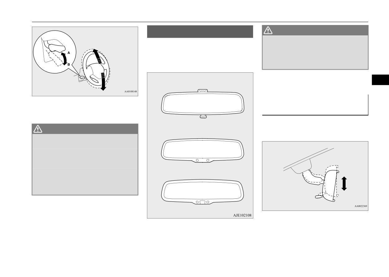
Inside rearview mirror
Inside rearview mirror
WARNING
N00511601532
z Do not attempt to adjust the inside rear-
Adjust the inside rearview mirror only after
view mirror while driving. This can be
dangerous.
making any seat adjustments so as to have a
Be sure to adjust the mirror before driv-
clear view to the rear of the vehicle.
ing.
Type 1
Adjust the inside mirror to maximize the
5
view through the rear window.
To adjust the vertical mirror
A- Wheel lock
B- Release
position
It is possible to move the mirror up and down
Type 2
WARNING
to adjust its position.
z After adjusting, make sure the lever is
secured in the locked (A) position.
z Do not attempt to adjust the steering
wheel while driving. This can be danger-
ous.
z When releasing the lever (moving it to the
Type 3
position (B)), be sure to hold the steering
wheel firmly. Otherwise, the steering
wheel may slip down too suddenly.
Features and controls
5-35

Inside rearview mirror
To adjust the mirror position
To reduce the glare
Type 2
It is possible to move the mirror up/down and
When the headlights of the vehicles behind
left/right to adjust its position.
you are very bright, the reflection factor of
Type 1
the rearview mirror is automatically changed
to reduce the glare.
The day/night knob (A) at the bottom of the
mirror can be used to adjust the mirror to
5
reduce the glare from the headlights of vehi-
cles behind you during night driving.
When the ignition switch is turned to the
“ON” position or the operation mode is put in
ON, the reflection factor of the mirror is auto-
1- Daytime position
matically changed.
2- Night position
NOTE
z Do not hang items on, or spray glass cleaner
on the sensor
(1), as reduced sensitivity
could result.
5-36
Features and controls

Outside rearview mirrors
Type 3
NOTE
WARNING
z
If you want to stop automatic mode, press
z Your passenger’s side mirror is convex.
When the headlights of the vehicles behind
the switch (3) for approximately 2 seconds
The objects you see in the mirror will look
you are very bright, the reflection factor of
and the indicator (1) will go off.
smaller and farther away than they
the rearview mirror is automatically changed
To return to automatic mode, press the
appear in a regular flat mirror.
to reduce the glare.
switch again or perform the following opera-
Do not use this mirror to estimate the dis-
tion.
tance of vehicles following you when
[Except for vehicles equipped with the Free-
changing lanes.
5
hand Advanced Security Transmitter
(F.A.S.T.-key)]
To adjust the mirror position
Turn the ignition switch to the “ON” position
after turning to “OFF” or “ACC” position.
N00549100144
[For vehicles equipped with the Free-hand
The outside rearview mirrors can be adjusted
Advanced Security Transmitter
(F.A.S.T.-
when the ignition switch or the operation
key)]
mode is in ON or ACC.
Put the operation mode in ON after putting
Move the lever (A) to the same side as the
the operation mode in OFF.
mirror you wish to adjust.
Normally, use the automatic mode. When the
Outside rearview mirrors
ignition switch is turned to the “ON” position
N00512200206
or the operation mode is put in ON, the green
Adjust the outside rearview mirrors only after
indicator
(1) illuminates and the reflection
making any seat adjustments so as to have a
factor of the mirror is automatically changed.
clear view to the rear of the vehicle.
NOTE
WARNING
z Do not hang items on, or spray glass cleaner
z Do not attempt to adjust the outside rear-
on the sensor
(2), as reduced sensitivity
view mirrors while driving. This can be
could result.
dangerous.
Be sure to adjust the mirrors before driv-
L- Left outside mirror adjustment
ing.
R- Right outside mirror adjustment
Features and controls
5-37

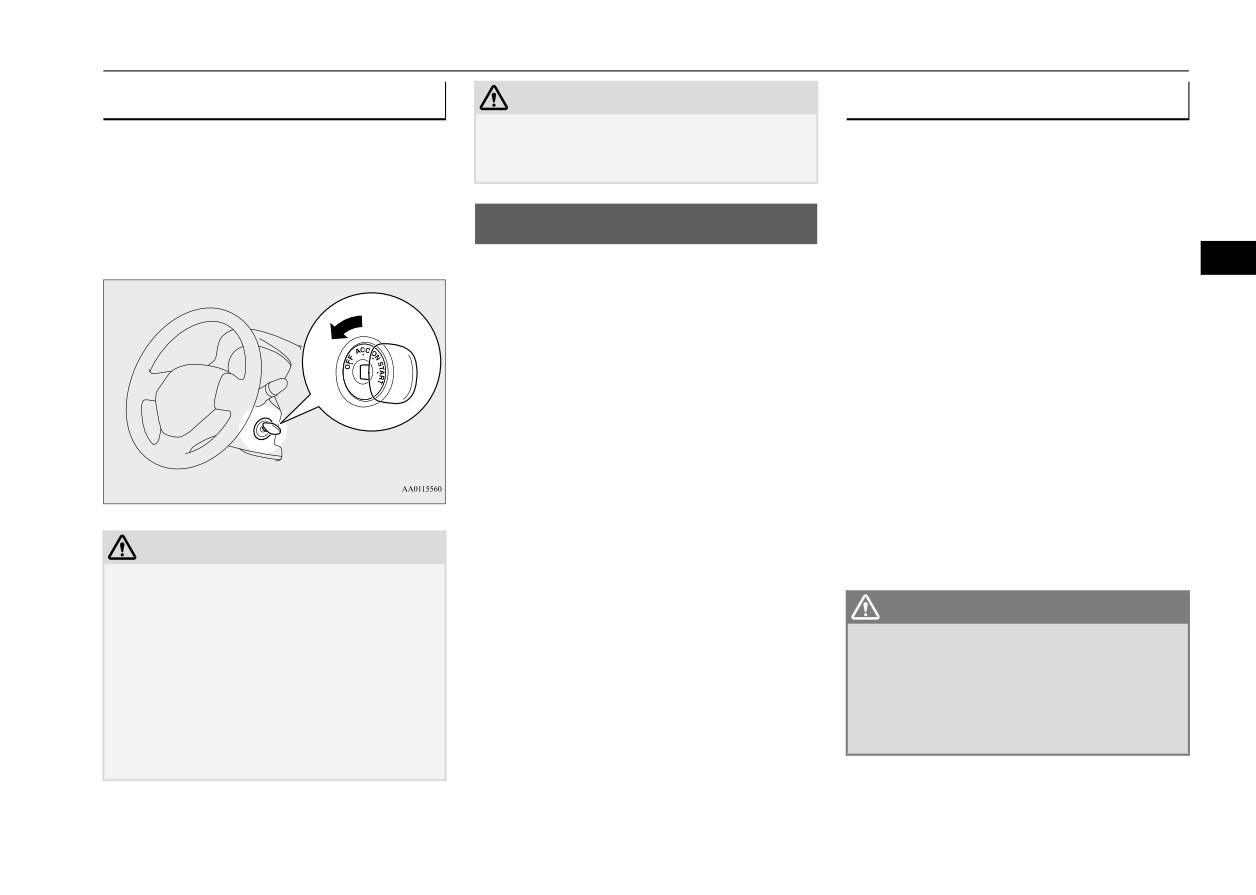
Ignition switch
Press the switch (B) to adjust the mirror posi-
Ignition switch
OFF
tion.
N00512401739
1- Up
[For vehicles equipped with the Free-hand
The engine is off. The key can be inserted and
2- Down
Advanced Security Transmitter (F.A.S.T.-
removed only when the switch is in this posi-
3- Right
key)]
tion.
4- Left
For information on operations for vehicles
equipped with the Free-hand Advanced Secu-
ACC
5
rity Transmitter
(F.A.S.T.-key), refer to
NOTE
“Free-hand Advanced Security Transmitter
Allows operation of some electrical accesso-
z After adjusting, return the lever to the “•”
(F.A.S.T.-key):
ries with the engine off.
(OFF) position (C).
Engine switch” on page 5-13.
[Except for vehicles equipped with the
ON
Free-hand Advanced Security Transmit-
To fold the mirror
ter (F.A.S.T.-key)]
N00549200099
The engine runs and all accessories can be
The outside mirror can be manually folded in
used.
towards the side window to prevent damage
when parking in tight locations.
START
Engages the starter. Release the key when the
engine starts.It will automatically return to
the “ON” position.
NOTE
z Your vehicle is equipped with an electronic
immobilizer. To start the engine, the ID code
(which the transponder inside the key sends)
must match the one registered to the immobi-
lizer computer. (Refer to “Electronic immo-
bilizer” on page 5-3.)
5-38
Features and controls
Starting the engine
To remove the key
CAUTION
Tips for starting
N00550901240
z Do not turn the key to the “START” position
1. Set the selector lever to the “P” (PARK)
when the engine is running, doing so could
z
Do not operate the starter motor continu-
position {continuously variable transmis-
damage the starter motor.
ously for longer than 15 seconds as this
sion (CVT)}.
could run the battery down or damage the
2. Turn the key to the “OFF” position and
starter motor. If the engine does not start,
Starting the engine
remove it.
turn the ignition switch back to the “OFF”
N00512601861
position, wait a few seconds, and then try
5
[For vehicles equipped with the Free-hand
again. Trying repeatedly with the engine
Advanced Security Transmitter (F.A.S.T.-
or starter motor still turning will damage
key)]
the starter mechanism.
For information on operation for vehicles
z
If the engine will not start because the bat-
equipped with the Free-hand Advanced Secu-
tery is weak or discharged, refer to
rity Transmitter
(F.A.S.T.-key), refer to
“Jump-starting the engine” (on page 8-2)
“Free-hand Advanced Security Transmitter
for instructions.
(F.A.S.T.-key): Starting and stopping the
z
A longer warm up period will only con-
engine” on page 5-17.
sume extra fuel. The engine is warmed up
enough for driving when the low coolant
[Except for vehicles
equipped with the
temperature indicator goes out.
Free-hand Advanced
Security Transmit-
Refer to “Low coolant temperature indi-
CAUTION
ter (F.A.S.T.-key)]
cator” on page 5-88.
z
If the engine is stopped while driving, the
power brake booster will cease to function
WARNING
and braking efficiency will deteriorate. Also,
the power steering system will not function
z Never run the engine in a closed or poorly
and it will require greater manual effort to
ventilated area any longer than is needed
operate the steering.
to move your vehicle out of the area. Car-
bon monoxide gas, which is odorless and
z
Do not leave the key in the “ON” position for
extremely poisonous, could build up and
a long time when the engine is not running.
cause serious injury or death.
Doing so will cause the battery to be dis-
charged.
Features and controls
5-39
Starting the engine
CAUTION
NOTE
NOTE
z Do not push-start the vehicle.
z On vehicles equipped with manual transaxle,
z Minor noises may be heard on engine start-
z Do not run the engine at high rpms or drive
the starter will not operate unless the clutch
up. These will disappear as the engine warms
at high speeds until the engine has had a
pedal is fully depressed (Clutch interlock).
up.
chance to warm up.
z Release the ignition switch as soon as the
6. On vehicles equipped with manual trans-
engine starts. Otherwise, the starter motor
When the engine is hard to start
axle, place the gearshift lever in the “N”
will be damaged.
5
(Neutral) position.
On vehicles equipped with continuously
After several attempts, you may experience
variable transmission (CVT), make sure
that the engine still does not start.
Starting the engine
the selector lever is in the “P” (PARK)
position.
1. Make sure that all electric devices, such
This model is equipped with an electronically
as lights, air conditioning blower and rear
controlled fuel injection system. This is a sys-
NOTE
window defogger, are turned off.
tem that automatically controls fuel injection.
z On vehicles equipped with CVT, the starter
2. While depressing the brake pedal {contin-
There is usually no need to depress the accel-
will not operate unless the selector lever is in
uously variable transmission (CVT)} or
erator pedal when starting the engine.
the “P” (PARK) or “N” (NEUTRAL) posi-
the clutch pedal (manual transaxle), press
The starter should not be run for more than 15
tion.
the accelerator pedal halfway and hold it
For safety reasons, start the engine in the “P”
there, then crank the engine. Release the
seconds at a time.
(PARK) position so that the wheels are
accelerator pedal, immediately after the
To prevent battery drain, wait a few seconds
locked.
between attempts to restart the engine.
engine starts.
1. Make sure all occupants are properly
7. Turn the ignition switch to the “ON” posi-
seated with seat belts fastened.
tion and make certain that all warning
2. Insert the ignition key.
lights are functioning properly before
3. Make sure the parking brake is applied.
starting the engine.
4. Press and hold the brake pedal down
8. Turn the ignition switch to the “START”
firmly with your right foot.
position without pressing the accelerator
5. Press and hold the clutch pedal all the way
pedal. Release the key when the engine
down (manual transaxle).
starts.
5-40
Features and controls

Manual transaxle (if so equipped)
3. If the engine still will not start, the engine
not indicate a problem. If this occurs, place
NOTE
could be flooded with too much gasoline.
the selector lever in the “P” (PARK) position
z During cold weather, shifting may be diffi-
While depressing the brake pedal (CVT)
and let the engine idle for at least 10 minutes.
cult until the transaxle lubricant has warmed
or the clutch pedal
(manual transaxle),
The transaxle will warm up, and you will be
up. This is normal and not harmful to the
push the accelerator pedal all the way
able to start normally.
transaxle.
down and hold it there, then crank the
Do not leave the vehicle during warm-up
engine for 5 to 6 seconds. Return the igni-
operation.
tion switch to the
“OFF” position and
To start
5
release the accelerator pedal. Wait a few
Manual transaxle (if so
seconds, and then crank the engine again
for 5 to 6 seconds while depressing the
equipped)
Press the clutch pedal all the way down and
brake pedal (CVT) or the clutch pedal
N00512701237
shift into 1st or “R” (Reverse) position, oper-
(manual transaxle), but do not push the
ating the gearshift lever slowly. Then gradu-
The shift pattern below is shown on the gear-
ally release the clutch pedal while depressing
accelerator pedal. Release the ignition
shift lever. Press the clutch pedal all the way
the accelerator pedal.
switch if the engine starts. If the engine
down while shifting gears.
fails to start, repeat these procedures. If
the engine still will not start, contact your
CAUTION
local Mitsubishi Motors dealer or a repair
z
Do not move the gearshift lever into reverse
facility of your choice for assistance.
while the vehicle is moving forward; doing
so will damage the transaxle.
z
Do not rest your foot on the clutch pedal
Startability of CVT vehicle with
because this will cause premature clutch
ambient temperature of -4 °F (-20
wear or damage.
°C) or lower
z
Do not coast in the “N” (Neutral) position
(illegal in many states).
z
Do not use the gearshift lever as a handrest,
When the ambient temperature is -4 °F (-20
because this can result in premature wear of
°C) or lower, it may not be possible to start
the transaxle shift forks.
from a standstill even with the selector lever
in the
“D” (DRIVE) or “R” (REVERSE)
position.
This phenomenon occurs because the trans-
axle has not warmed up sufficiently; it does
Features and controls
5-41
Manual transaxle (if so equipped)
Shift point
Upshift speeds
NOTE
Upshifting
z If it is hard to shift into
1st, depress the
N00512900131
4th gear to 5th gear
45 mph (72 km/h)
clutch pedal a second time; the shift will then
For the best fuel economy and performance in
be easier.
using your manual transaxle, upshift as listed
Downshifting
z To shift into reverse from 5th gear, move the
below.
gearshift lever to the “N” (Neutral) position,
N00513000096
and then shift it into reverse.
It is recommended that you downshift to a
At low altitude locations, shift at the vehicle
z To avoid grinding noises when shifting into
lower gear when needed to maintain the
5
speeds listed. Upshifting earlier during cruise
reverse, wait approximately 3 seconds with
conditions
(relatively steady speeds) will
desired speed, according to the table.
the clutch pedal depressed when the vehicle
improve your fuel economy.
Avoid downshifting at too high a speed. The
is stationary.
engine may suffer damage.
Upshift speeds
To maintain a safe speed and prolong brake
Shift point
life, shift down to 2nd or 1st when descend-
Proper shift points
Acceleration
Cruise
ing a steep hill.
N00537400065
1st gear to
15 mph
15 mph
Downshifting is also important to avoid “lug-
Always use care to change the gear with the
2nd gear
(24 km/h)
(24 km/h)
ging” the engine at too low a speed, such as
vehicle speed matched to the engine speed.
2nd gear to
28 mph
19 mph
when turning a corner or when driving up a
Proper shifting will improve fuel economy
3rd gear
(45 km/h)
(31 km/h)
steep hill.
and prolong engine life.
3rd gear to
36 mph
33 mph
4th gear
(58 km/h)
(53 km/h)
Recommended downshifting speed
CAUTION
4th gear to
45 mph
45 mph
z Avoid downshifting that may cause the
5th gear
(72 km/h)
(72 km/h)
Downshifting speed
Shift point
tachometer pointer to enter the red zone.
This puts the engine at risk of being dam-
Under 20 mph
Shift down from cur-
aged.
At high altitude locations, upshift as listed
(32 km/h)
rent gear to 2nd gear.
below.
20 to 30 mph (32 to
Shift down from cur-
48 km/h)
rent gear to 3rd gear.
Shift point
Upshift speeds
1st gear to 2nd gear
15 mph (24 km/h)
2nd gear to 3rd gear
25 mph (40 km/h)
3rd gear to 4th gear
40 mph (64 km/h)
5-42
Features and controls
Continuously variable transmission (CVT) (if so equipped)
driving conditions. This helps achieve
Driving precautions
NOTE
smooth driving and excellent fuel efficiency.
N00513100244
z The selector lever cannot be moved from “P”
z Do not use the gearshift lever as a han-
(PARK) to another position if the ignition
drest. This can result in premature wear of
DRIVING UPHILL
switch is set to the “OFF” or “ACC” posi-
the transaxle shift forks.
tion, or if the key has been removed, or oper-
ation mode is in “OFF” or “ACC”, or if the
The transmission prevents unnecessary
brake pedal is not pressed and held down.
Maximum possible driving speed
upshifts even when the accelerator pedal is
released and ensures smooth driving.
5
The CVT selects an optimum ratio automati-
Shift
Maximum possible driving
cally when the selector lever is in the “D”
DRIVING DOWNHILL
points
speed
(DRIVE) position, depending on the speed of
1st gear
28 mph (45 km/h)
the vehicle and the position of the accelerator
According to the conditions, the transmission
pedal.
2nd gear
53 mph (85 km/h)
will automatically shift to a lower gear ratio
3rd gear
78 mph (125 km/h)
to achieve stronger engine braking. This may
help reduce your need to use the service
4th gear
105 mph (170 km/h)
brake.
z The table above shows the maximum rec-
ommended driving speed for in each gear.
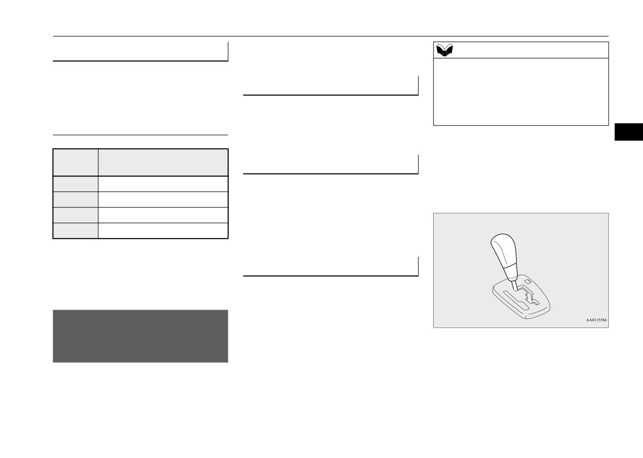
Selector lever operation
Do not drive near or at these speeds for
N00560301087
prolonged periods of time.
As an additional safety precaution, models
equipped with a continuously variable trans-
mission have a shift-lock device that holds
Continuously variable
the selector lever in the “P” (PARK) position.
transmission (CVT)
(if so
To move the selector lever from the
“P”
equipped)
(PARK) position to another position, follow
the steps below.
N00560200050
The CVT will automatically and continuously
1. Press and hold the brake pedal down.
change its gear ratio depending on road and
2. Move the selector lever to the desired
position.
Features and controls
5-43

Continuously variable transmission (CVT) (if so equipped)
If you need to move the vehicle, shift the
NOTE
selector lever as follows.
z
To prevent mistakes in operating the lever,
make sure you stop briefly at each position.
1. Make sure the parking brake is fully
After operating, check the position in the
applied.
multi-information display.
2. Stop the engine if it is running.
z
If the brake pedal is not depressed and held,
3. Insert a screwdriver with a cloth over its
the shift-lock device activates to prevent the
tip into the notch (A) of the cover. Pry
selector lever from being moved from the
5
gently as shown to remove the cover.
“P” (PARK) position.
z For a shift indicated by
in the illustra-
tion, depress the brake pedal before moving
Set the selector lever in the gate to
the selector lever. If you attempt to move the
operate while the brake pedal is
selector lever before depressing the brake
depressed.
pedal, the selector lever may not move.
Set the selector lever in the gate to
operate.
When the selector lever cannot be
shifted from the “P” (PARK) posi-
WARNING
tion
z
Always press the brake pedal when shift-
N00563300049
4. Depress the brake pedal with the right
ing the selector lever into a selector posi-
When the selector lever cannot be shifted
foot.
tion from the “N” (NEUTRAL) position.
from the
“P” (PARK) position to another
5. Insert a screwdriver in the shift-lock
When beginning to drive, do not shift the
position while the brake pedal is pressed and
release hole (B). Shift the selector lever to
selector lever from the “N” (NEUTRAL)
the
“N”
(NEUTRAL) position while
position while pressing the accelerator
held down with the ignition switch or the
pedal. This will cause the vehicle to
operation mode in ON, the battery may be flat
pressing the screwdriver down.
“jump” forward or backward.
or the shift-lock mechanism may be malfunc-
tioning.
Immediately have your vehicle checked by an
authorized Mitsubishi Motors dealer or a
repair facility of your choice.
5-44
Features and controls

Continuously variable transmission (CVT) (if so equipped)
Selector lever positions
WARNING
N00560601093
z
Never move the selector lever to the “N”
(NEUTRAL) position while driving since
you could accidentally slip it into the “P”
“P” PARK
(PARK) or
“R”
(REVERSE) position,
damaging the transmission.
This position locks the transmission to pre-
z
To prevent the vehicle from rolling when
vent the vehicle from moving. The engine can
stopped on a slope, the engine should be
5
be started from the “P” (PARK) position.
started in the “P” (PARK) position, not in
“N” (NEUTRAL) position.
z
To prevent rolling, always keep your foot
“R” REVERSE
on the brake pedal when the vehicle is in
“N” (NEUTRAL) position, or when shift-
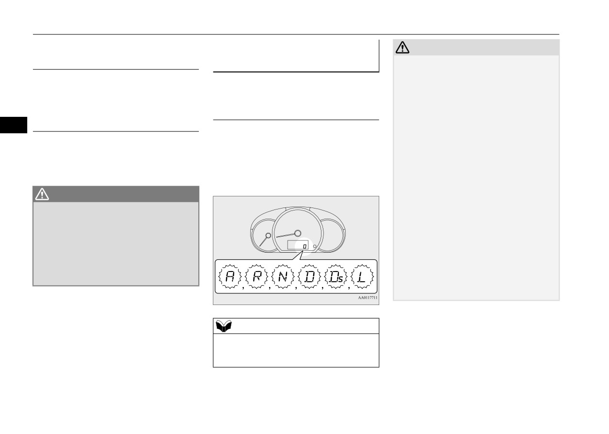
Selector lever position display
Move the lever to this position only after the
ing into or out of “N” (NEUTRAL) posi-
N00560400078
vehicle has come to a complete stop.
tion.
When the ignition switch is turned to the
“ON” position or the operation mode is put in
CAUTION
“D” DRIVE
ON, the selector lever position is shown on
z Never shift into the
“P” (PARK) or “R”
the multi-information display.
(REVERSE) position while the vehicle is in
motion. If the lever is shifted into the “P”
This position is used for most city and high-
(PARK) or “R” (REVERSE) position while
way driving. The transmission will automati-
the vehicle is in motion, the transmission
cally and continuously change its gear ratio
may be damaged.
depending on road and driving conditions.
CAUTION
“N” NEUTRAL
z To prevent transmission damage, never shift
into the “D” (DRIVE) position from the “R”
At this position, the transmission is disen-
(REVERSE) position while the vehicle is in
gaged. It is the same as the neutral position on
motion.
a manual transaxle and should be used when
the vehicle is not moving for an extended
length of time during driving, such as in a
traffic jam.
Features and controls
5-45
Continuously variable transmission (CVT) (if so equipped)
“Ds” DOWNSHIFT & SPORTY
When a malfunction occurs in
CAUTION
DRIVING
the automatic transaxle
z
If a malfunction occurs in the CVT while
driving, the indicator will blink.
N00549500018
In this case, immediately park your vehicle
Use when engine braking is needed, or for
in a safe place and follow these procedures:
high-power sport drive.
When the selector lever position
[If the indicator blinks rapidly (once per sec-
indicator blinks
ond), the CVT fluid is overheating.]
“L” LOW
N00574601049
Park your vehicle in a safe place but do not
5
When the selector lever position indicator
turn off the engine. Move the selector lever
to the
“P” (PARK) position and open the
blinks while you are driving, there could be a
This position is for driving up very steep hills
engine hood. Keep the engine, idling.
malfunction in the automatic transaxle system
and for engine braking at low speeds when
After a while, move the selector lever into
or CVT fluid temperature becomes abnor-
driving down steep hills.
any position other than “P” (PARK) position
mally high.
and confirm that the indicator stops blinking.
It is safe to continue driving if the indicator
WARNING
no longer blinks.
z This position can be used for maximum
If the indicator continues blinking, contact
engine braking.
an authorized Mitsubishi Motors dealer or
Be very careful not to shift into
“L”
repair facility of your choice immediately.
(LOW) suddenly.
[If the indicator blinks slowly (once per 2
Sudden engine braking may cause the
seconds), the CVT may be operating in fail-
tires to skid.
safe mode due to a malfunction.]
Select this position according to the road
Have the vehicle inspected at an authorized
conditions and vehicle speed.
Mitsubishi Motors dealer or repair facility of
your choice immediately.
NOTE
z The “A” indicator blinks only if the CVT
selector lever switch is broken.
It is not seen during normal driving.
5-46
Features and controls
Continuously variable transmission (CVT) (if so equipped)
Operation of the CVT
CAUTION
Waiting
N00560801095
z
Use the selector lever in the correct shift
position in accordance with driving condi-
For short waiting periods, such as at traffic
CAUTION
tions.
lights, the vehicle can be left in selector lever
z
Before selecting a position with the engine
Never coast downhill backward in the driv-
position and held stationary with the service
running and the vehicle stationary, firmly
ing shift position
“D”
(DRIVE),
“Ds”
brake.
depress the brake pedal to prevent the vehi-
(DOWNSHIFT & SPORTY DRIVING), “L”
For longer waiting periods with the engine
cle from creeping.
(LOW) or coast forward in the
“R”
running, place the selector lever in the “N”
5
The vehicle will begin to move as soon as the
(REVERSE) position.
CVT is engaged, especially when the engine
Engine stopping and increased brake pedal
(NEUTRAL) position and apply the parking
speed or idle speed is high, or with the air
and steering effort could lead to an accident.
brake, while holding the vehicle stationary
conditioning operating.
z
Do not rev the engine with the brake pedal
with the service brake.
Do not release the brake pedal until you are
pressed when the vehicle is stationary.
Prior to moving off after having stopped the
ready to drive away.
This can damage the CVT.
vehicle, make sure that the selector lever is in
z
Depress the brake pedal with the right foot at
Also, when you depress the accelerator pedal
“D” (DRIVE) position.
all times.
while holding down the brake pedal with the
Using the left foot could cause driver move-
selector lever in the “D” (DRIVE) position,
ment delay in case of an emergency.
the engine revolutions may not rise as high
CAUTION
as when performing the same operation with
z To avoid transmission overheating, never try
z
To prevent sudden acceleration, never run
the selector lever in the “N” (NEUTRAL)
to keep your vehicle stationary on a hill by
the engine at high rpms when shifting from
position.
using the accelerator pedal. Always apply
the “P” (PARK) or “N” (NEUTRAL).
the parking brake and/or service brake.
z
Operating the accelerator pedal while the
z Do not rev the engine unnecessarily while
other foot is resting on the brake pedal will
Passing acceleration
the vehicle is stationary. Unexpected acceler-
affect braking efficiency and may cause pre-
ation may occur if the selector lever is in a
mature wear of brake pads.
To gain extra acceleration in “D” (DRIVE)
position other than
“P”
(PARK) or
“N”
position (when passing another vehicle) push
(NEUTRAL).
the accelerator to the floor. The CVT will
automatically downshift.
Parking
To park the vehicle, first bring it to a com-
plete stop, fully engage the parking brake,
Features and controls
5-47
Service brake
and then move the selector lever to the “P”
If the power brake unit or either of the two
WARNING
(PARK) position.
brake hydraulic systems stops working prop-
z
Do not leave any objects near the brake
erly, the rest of the brake system will still
pedal or let a floor mat slide under it;
work, but the vehicle will not slow down as
When the CVT makes no speed
doing so could prevent the full pedal
quickly.
change
stroke that would be necessary in an
You will know this has happened if you find
emergency. Make sure that the pedal can
be operated freely at all times. Make sure
you need to press the brake down farther, or
If the CVT does not shift while driving, or
the floor mat is securely held in place.
harder when slowing down or stopping, or if
5
your vehicle does not pick up enough speed
the brake warning light and the warning dis-
when starting on an uphill slope, it may be
play in the multi-information display come
that there is something unusual happening in
CAUTION
on. Have the brake system repaired at an
the transmission. Have your vehicle checked
authorized Mitsubishi Motors dealer or a
z
It is important not to drive the vehicle with
at an authorized Mitsubishi Motors dealer or
your foot resting on the brake pedal when
repair facility of your choice immediately.
a repair facility of your choice immediately.
braking is not required. This practice can
result in very high brake temperatures, pre-
WARNING
mature lining wear, and possible damage to
Service brake
z
Never coast downhill with the engine OFF.
the brakes.
N00517501328
Keep the engine running whenever your
vehicle is in motion. If you turn off the
engine while driving, the power brake
Brake pedal
Power brakes
booster will stop working and your brakes
N00517600436
will not work as well.
Overuse of the brake can cause weakening,
z
If the power assist is lost or if either brake
Your vehicle is equipped with power brakes
resulting in poor brake response and prema-
hydraulic system stops working properly,
for more braking force with less brake pedal
ture wear of the brake pads.
take your vehicle to an authorized
effort.
When driving down a long or steep hill, use
Mitsubishi Motors dealer or a repair facil-
Your brakes are designed to operate at full
ity of your choice immediately.
engine braking by moving the selector lever
capacity, even if the power assist is not being
to “Ds” (DOWNSHIFT & SPORTY DRIV-
used.
ING) or “L” (LOW) position.
If the power assist is not being used, the effort
needed to press the brake pedal is greater.
If you should lose the power assist for some
reason, the brakes will still work.
5-48
Features and controls
Hill start assist
2. On vehicles with manual transaxle, place
Brake pad wear alarm
CAUTION
the gearshift lever into the 1st position.
N00550700124
z
Do not overly rely on the hill start assist to
On vehicles with CVT, place the selector
prevent backwards movement of the vehicle.
The disc brakes have an alarm that makes a
lever into the “D” (DRIVE) position.
Under certain circumstances, even when hill
metallic squeal when the brake pads have
start assist is activated, the vehicle may
worn down enough to need service.
move backwards if the brake pedal is not suf-
NOTE
If you hear this sound, have the brake pads
ficiently depressed, if the vehicle is heavily
z When reversing on an uphill slope, place the
replaced at an authorized Mitsubishi Motors
loaded, or if the road is very steep or slip-
gearshift lever or selector lever into the “R”
dealer or a repair facility of your choice.
5
pery.
position.
z
The hill start assist is not designed to keep
the vehicle stopped in place on uphill slopes
WARNING
3. Release the brake pedal and the hill start
for more than 2 seconds.
z Driving with worn brake pads will make it
assist will maintain the braking force
z
When facing uphill, do not rely on using the
harder to stop, and can cause an accident.
applied while stopped for approximately 2
hill start assist to maintain a stopped position
seconds.
as an alternative to depressing the brake
pedal.
4. Depress the accelerator pedal and the hill
Hill start assist
Doing so could cause an accident.
start assist will gradually decrease the
N00562601127
z
Do not perform the following operation
braking force as the vehicle starts moving.
while the hill start assist is operating.
The hill start assist makes it easy to start off
[Except for vehicles equipped with the
NOTE
on a steep uphill slope by preventing the
F.A.S.T.-key]
z The hill start assist is activated when all of
vehicle from moving backwards. It keeps the
Turn the ignition switch to the
“OFF” or
the following conditions are met.
brakes applied for approximately 2 seconds
“ACC” position.
• The engine is running.
when you move your foot from the brake
[Vehicles equipped with the F.A.S.T.-key]
(The hill start assist will not be activated
pedal to the accelerator pedal.
Put the operation mode in OFF or ACC. The
while the engine is starting or immediately
hill start assist could stop operating, which
after the engine is started.)
could result in an accident.
To operate
N00562701131
1. Stop the vehicle completely using the
brake pedal.
Features and controls
5-49
Brake assist system
If the brake pedal is depressed suddenly, the
NOTE
Warning indicator
brakes will be applied with more force than
• On vehicles with manual transaxle, the
N00562800092
usual.
gearshift lever is in the following position.
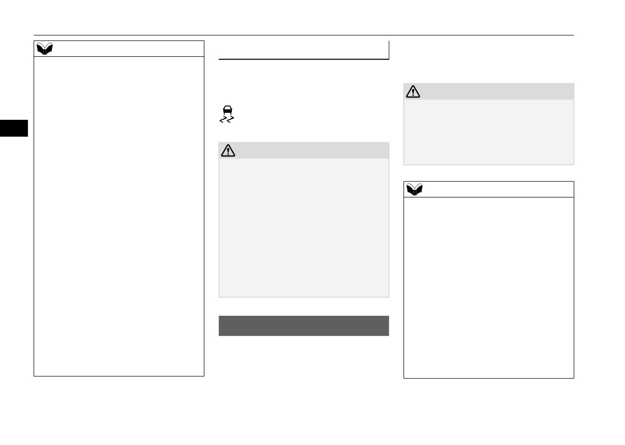
If an abnormal condition occurs in the sys-
[When starting an uphill slope forwards.]
tem, the following indicator will turn on.
The gearshift lever is in any position other
CAUTION
than “R” (Reverse).
z
The brake assist system is not a device
(The hill start assist will operate, even if the
- ASC indicator
designed to exercise braking force greater
gearshift lever is in the “N” (Neutral) posi-
than its capacity. Make sure to always keep a
5
tion.)
sufficient distance between your vehicle and
[When starting an uphill slope backwards.]
a vehicle in front of you without relying too
CAUTION
The gearshift lever is in the “R” (Reverse)
much on the brake assist system.
position.
z
If the warning is displayed, the hill start
(The hill start assist will not operate when
assist will not operate. Start off carefully.
the gearshift lever is in the “N” (Neutral)
z
Park your vehicle in a safe place and stop the
NOTE
position.)
engine.
z
Once the brake assist system is operational,
• On vehicles with CVT, the selector lever is
Restart the engine and check whether the
it maintains great braking force even if the
in any position other than “P” (PARK) or
indicator goes out, in which case the hill start
brake pedal is lightly released.
“N” (NEUTRAL).
assist is again working normally.
To stop its operation, completely remove
• The vehicle is completely stationary, with
If they remain displayed or reappear fre-
your foot from the brake pedal.
the brake pedal depressed.
quently, it is not necessary to stop the vehicle
z
When the brake assist system is in use while
immediately, but the vehicle should be
• The parking brake is released.
driving, you may feel as if the depressed
inspected by an authorized Mitsubishi
z
The hill start assist will not operate if the
brake pedal is soft, the pedal moves in small
Motors dealer or a repair facility of your
accelerator pedal is depressed before the
motions in conjunction with the operation
choice as soon as possible.
brake pedal is released.
noise, or the vehicle body and the steering
z
The hill start assist also operates when
wheel vibrate. This occurs when the brake
reversing on an uphill slope.
assist system is operating normally and does
z
When the hill start assist is activated, you
Brake assist system
not indicate faulty operation. Continue to
may feel the operating sound or vibration
N00567301116
depress the brake pedal.
from under the body.
z
When the anti-lock brake system warning
The brake assist system is a device assisting
This is a normal result of the hill start assist
light is illuminated, the brake assist system is
drivers who cannot depress the brake pedal
operation, and does not indicate a problem.
not functioning.
firmly such as in emergency stop situations
and provides greater braking force.
5-50
Features and controls

Anti-lock braking system
z When the anti-lock braking system is in
Anti-lock braking system
Anti-lock braking system warn-
use, you may feel the brake pedal vibrat-
N00517900338
ing light
ing and hear a unique sound. It may also
The anti-lock braking system helps prevent
feel as if the pedal resists being pressed.
N00531600674
the wheels from locking up when braking.
In this situation, simply hold the brake
This helps maintain vehicle drivability and
pedal down firmly. Do not pump the
steering wheel handling.
brake, which will result in reduced
braking performance.
5
Driving hints
CAUTION
z
When using the anti-lock brakes (sudden
z
The anti-lock braking system cannot prevent
braking), steering is slightly different
accidents. It is your responsibility to take
from normal driving conditions. Use the
safety precautions and to drive carefully.
steering wheel carefully.
z
To prevent failure of the anti-lock braking
z
Always keep a safe distance from the
system, be sure all 4 wheels and tires are the
vehicle in front of you. Even if your vehi-
same size and the same type.
If there is a malfunction in the system, the
cle is equipped with the anti-lock braking
anti-lock braking system warning light will
system, leave a greater braking distance
come on.
when:
NOTE
Under normal conditions, the ABS warning
• Driving on gravel or snow-covered
z
You may feel the operating sound or vibra-
light comes on when the ignition switch is
roads.
tion from under the body when driving
turned to the “ON” position or the operation
• Driving on uneven road surfaces.
immediately after starting the engine. This is
a normal result the anti-lock braking system
mode is put in ON and goes off a few seconds
z
Operation of anti-lock braking system is
makes when performing a self-check. It does
later.
not restricted situations where brakes are
not indicate a problem.
applied suddenly. This system may also
z
The anti-lock braking system can be used
prevent the wheels from locking when
CAUTION
after the vehicle has reached a speed over
you drive over manholes, steel roadwork
z Any of the following indicates that the anti-
approximately
6 mph (10 km/h). It stops
plates, road markings, or any uneven road
lock braking system is not functioning and
working when the vehicle slows below 3
surface.
only the standard brake system is working.
mph (5 km/h).
(The standard brake system is functioning
normally.) If this happens, take your vehicle
to an authorized Mitsubishi Motors dealer or
a repair facility of your choice.
Features and controls
5-51