Mitsubishi L200 (2020 year). Manual in english - page 17
USB input terminal*
See the following section for details on how
Type 2
NOTE
to play music files.
Refer to “Listen to an iPod*” on pages 7-31,
z Do not connect the USB memory device to
the USB input terminal directly.
7-55.
The USB memory device may be damaged.
Refer to “Listen to Audio Files on a USB De-
vice*” on pages 7-33, 7-57.
5. To remove the USB connector cable,
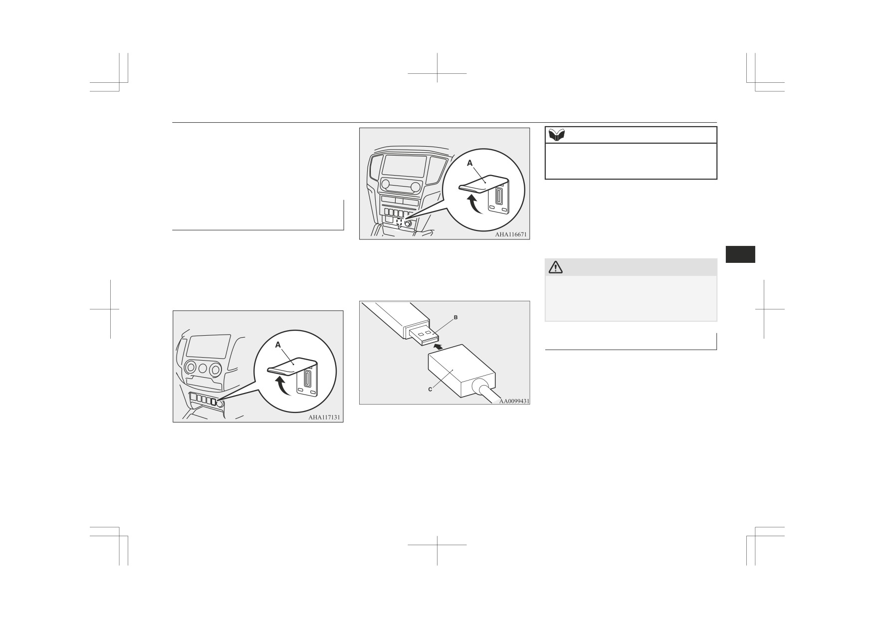
How to connect a USB memory
turn the ignition switch to the “LOCK”
device
position or put the operation mode in
OFF first and perform the installation
1. Park your vehicle in a safe place and
steps in reverse.
turn the ignition switch to the “LOCK”
position or put the operation mode in
7
3. Connect a commercially available USB
OFF.
CAUTION
connector cable (C) to the USB memory
2. Open the cover (A) (if so equipped) on
device (B).
z After removing the USB connector cable, be
the centre console.
sure to close the terminal cover (if so equip-
ped). Entry of foreign matter into the termi-
nal may cause a malfunction.
Type 1
How to connect an iPod
1. Park your vehicle in a safe place and
turn the ignition switch to the “LOCK”
position or put the operation mode in
OFF.
2. Open the USB input terminal cover (A)
(if so equipped) on the centre console.
4. Connect the USB connector cable to the
USB input terminal.
For pleasant driving
7-93

USB input terminal*
5. To remove the connector cable, turn the
Type 1
For vehicles equipped with the
ignition switch to the “LOCK” position
LW/MW/FM radio/CD player
or put the operation mode in OFF first
Refer to “Listening to an iPod” on page 7-55.
and perform the installation steps in re-
“Listening to Audio Files on a USB Device”
verse.
on page 7-57 and “Audio Files (MP3/WMA/
AAC)” on page 7-43.
CAUTION
For vehicles equipped with the DISPLAY
z After removing the connector cable, be sure
to close the terminal cover (if so equipped).
AUDIO
Entry of foreign matter into the terminal
Refer to the separate owner’s manual.
may cause a malfunction.
7
Type 2
For vehicles equipped with the Smart-
phone Link Display Audio
Types of connectable devices
and supported file specifica-
Refer to the separate owner’s manual.
tions
For vehicles equipped with the
MITSUBISHI Multi-Communication Sys-
Except for vehicles equipped
tem (MMCS)
with the Bluetooth® 2.0 inter-
Refer to the separate owner’s manual.
face
For details about the types of connectable de-
For vehicles equipped with the
vices and supported file specifications, refer
Bluetooth® 2.0 interface
3. Connect the connector cable to the iPod.
to the following pages and manuals.
For details about the types of connectable de-
vices and supported file specifications, refer
For vehicles equipped with the AM/FM ra-
NOTE
to the following sections.
dio/CD player with AUX
z Use a genuine connector cable from Apple
Inc.
Refer to “Listen to an iPod” on page 7-31,
Device types
“Listen to Audio Files on a USB Device*” on
Devices of the following types can be con-
page 7-33 and “Audio Files
(MP3/WMA/
4. Connect the connector cable to the USB
nected.
AAC)” on page 7-21.
input terminal.
7-94
For pleasant driving
HDMI terminal*
Model name
Condition
NOTE
Item
Condition
Storage capacity of
Number of folders
700
z You can charge your iPod by connecting it to
256 Mbytes or more
the USB input terminal when the ignition
USB memory device
Number of files
65,535
(File System is
switch or the operation mode is in ON or
ACC.
FAT16/32)
z
Do not keep your USB memory device or
HDMI terminal*
Models other than
Digital audio player
iPod in your vehicle.
USB memory devi-
supporting mass stor-
z It is recommended that you back up files in
You can connect a commercially available
ces and iPods
age class
case of data damage.
HDMI device such as a video camera and a
z
Do not connect to the USB input terminal
In some countries, for connectable device
any device (hard disk, card reader, memory
smart phone to the HDMI terminal (A).
types for
“iPod*,”
“iPod classic*,”
“iPod
reader, etc.) other than the connectable devi-
7
nano*,” “iPod touch*” and “iPhone*,” access
ces specified in the previous section. The de-
vice and/or data may be damaged. If any of
the MITSUBISHI MOTORS website.
these devices was connected by mistake, re-
Please read and agree to the “Warning about
move it after turning the ignition switch to
Links to the Web Sites of Other Companies”.
the “LOCK” position or putting the opera-
The websites mentioned above may connect
tion mode in OFF.
you to websites other than the MITSUBISHI
MOTORS website.
File specifications
ucts/ index.html
You can play music files of the following
*: “iPod,” “iPod classic,” “iPod nano,” “iPod
specifications that are saved in a USB memo-
touch” and
“iPhone” are registered trade-
ry device or other device supporting mass
marks of Apple Inc. in the United States and
storage class. When you connect your iPod,
playable file specifications depend on the
NOTE
other countries.
connected iPod.
For details, refer to the separate owner’s
z
manual for a Smartphone Link Display Au-
NOTE
Item
Condition
dio.
z Depending on the type of the USB memory
MP3, WMA, AAC,
device or other device connected, the con-
File format
WAV
nected device may not function properly or
the available functions may be limited.
Maximum number of
z It is recommended to use an iPod with firm-
levels
Level 8
ware updated to the latest version.
(including the root)
For pleasant driving
7-95

Sun visors
To connect
Card holder
Vanity mirror
1. Park your vehicle in a safe place and
Cards can be slipped into the holder (A) on
A vanity mirror is fitted to the back of the
turn the ignition switch to the “LOCK”
the back of the sun visor.
sun visor on the passenger side.
position or put the operation mode in
OFF.
Type 1
2. Connect a commercially available
HDMI cable to the HDMI device.
3. Connect a HDMI cable to the HDMI ter-
minal.
4. To remove the HDMI cable, perform the
7
installation steps in reverse.
Sun visors
Type 2
Ashtray
CAUTION
z Put out matches and cigarettes before they
are placed in the ashtray.
z Don’t put papers and other things that burn
into your ashtrays. If you do, cigarettes or
other smoking materials could set them on
fire, causing damage.
z
Always close the ashtray. If left open, other
1- To eliminate front glare
cigarette butts in the ashtray may be rekin-
2- To eliminate side glare
dled.
7-96
For pleasant driving

Cigarette lighter
To use the moveable ashtray, open the lid.
After use, insert the cigarette lighter to its
Cigarette lighter
original position in the socket.
The cigarette lighter can be used while the ig-
nition switch or the operation mode is in ON
NOTE
or ACC.
z
Do not leave the cigarette lighter removed
from its socket, because the socket might be-
Type 1
come clogged by foreign material and be
short-circuited.
CAUTION
7
Do not touch the heating element or the cig-
z
arette lighter housing, hold the knob only to
Mounting position for movea-
prevent burns.
ble ashtray
Do not allow children to operate or play with
z
the cigarette lighter as burns may occur.
The moveable ashtray can be fitted at the in-
z
Something is wrong with the cigarette light-
dicated position.
er if it does not pop back out within approxi-
Type 2
mately 30 seconds of being pushed in.
Pull it out and have the problem corrected at
For the front seat
MITSUBISHI MOTORS Authorized Serv-
ice Point.
z
Do not use any electric appliance that is not
approved by MITSUBISHI MOTORS. Do-
ing so could damage the socket. If you used
the cigarette lighter after damaging the sock-
et, the cigarette lighter might pop out or fail
to come out after being pushed in.
For the rear seat
1- Push all the way in.
The cigarette lighter will automatically return
to its original position with a “click” when
ready. Pull it out for use.
For pleasant driving
7-97

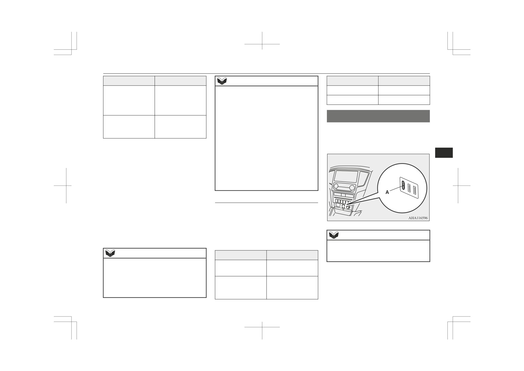
Accessory socket
There are two USB ports (for charging) loca-
CAUTION
CAUTION
ted on the back of the floor console box.
z When the cigarette lighter socket is used as a
z Be sure to use a “plug-in” type accessory op-
When using the USB port (for charging),
power source for an electric appliance, be
erating at 12 V and at 120 W or less.
open the lid and connect the USB connector
sure that the electric appliance operates at
When using more than one socket at the
cable to it.
12 V and has an electric capacity of 120 W
same time, make sure that the electrical ac-
or less. In addition, long use of the electric
cessories are 12 V accessories and that the
appliance without running the engine may
total power consumption does not exceed
run down the battery.
120 W.
z
Long use of the electric appliance without
running the engine may run down the bat-
Accessory socket
tery.
z
When the accessory socket is not in use, be
7
The accessory socket can be used while the
sure to close the lid, because the socket
might become clogged by foreign material
ignition switch or the operation mode is in
and be short-circuited.
ON or ACC.
To use a plug-in type accessory, open the lid,
and insert the plug in the accessory socket.
USB port (for charging)*
The USB port (for charging) can be used as a
CAUTION
power source of the USB appliances when
z
When the USB port (for charging) is not in
the ignition switch or the operation mode is
use, be sure to close the lid, because the
in ON or ACC.
USB port (for charging) might be short-
circuited by clogging foreign materials and
the connected devices and the USB port (for
charging) might be damaged.
z
Insert the USB connector cable in the USB
port (for charging) firmly.
If the USB connector cable does not insert in
it firmly, it may become extremely hot and
the fuses may blow.
7-98
For pleasant driving
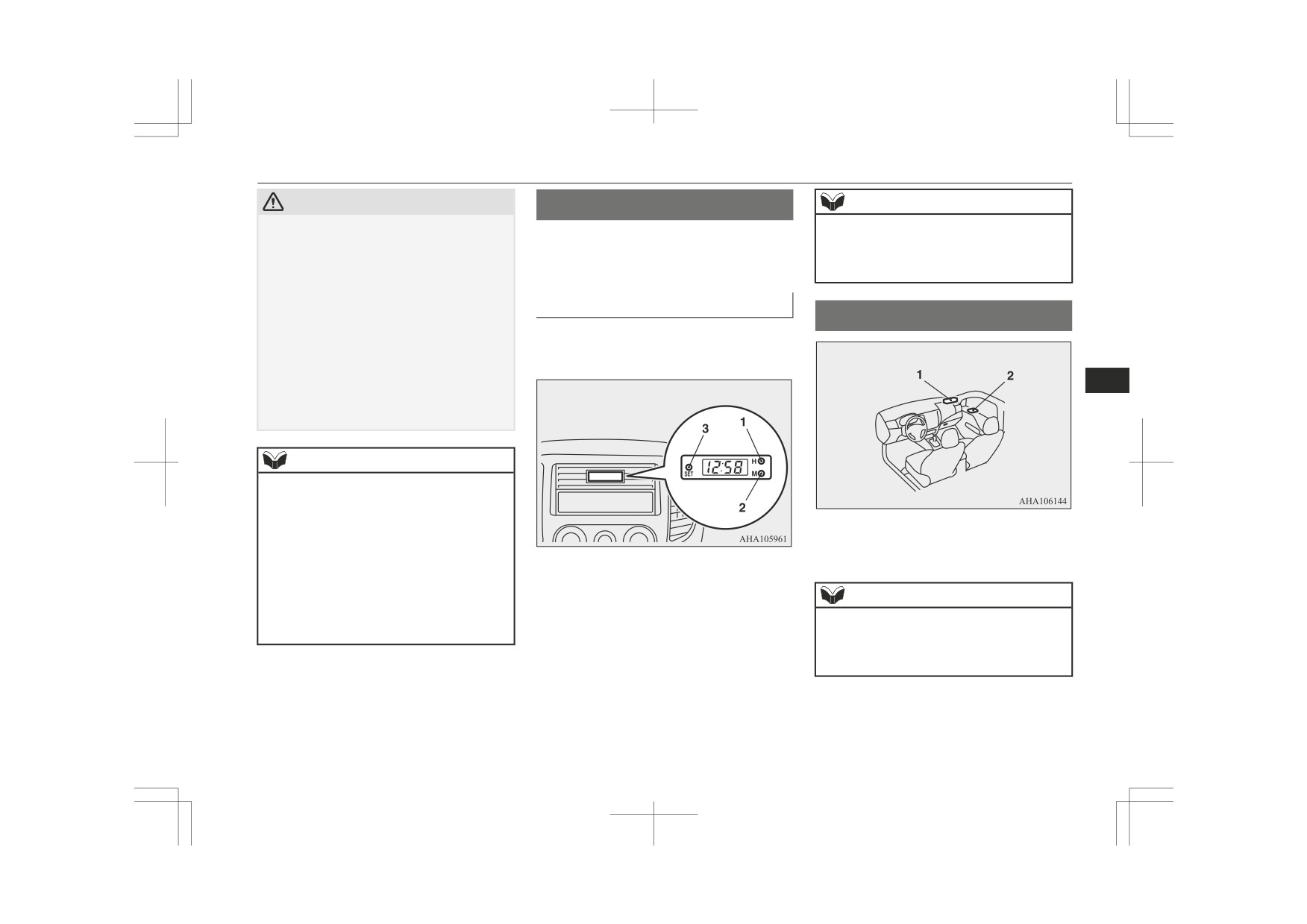
Digital clock*
CAUTION
Digital clock*
NOTE
z
Be sure that the power consumption does not
z If the battery cables are disconnected during
The digital clock indicates the time with the
exceed 10.5 W {The peak outlet current or
repairs or for any other reason, reset the
voltage of the USB port (for charging) is DC
ignition switch or the operation mode is in
clock to the correct time after they are recon-
5 V-2.1 A}.
ON or ACC.
nected.
The connected devices or the USB port (for
charging) may be damaged.
To set the time
z
Do not use the reversible USB connector ca-
Interior lamps
ble on the USB connector board that is loca-
Set the time by pressing the various buttons
ted in the centre.
as described below.
The USB port (for charging) might be dam-
aged.
7
z
Long use of the electric appliance without
running the engine may run down the bat-
tery.
NOTE
z
These USB ports (for charging) can be used
only as a power source. They do not connect
to the audio devices of the vehicles.
z
Do not charge many mobile devices together
1- Front room & map lamps*
by using a multi-plug adapter of the USB
port (for charging).
2- Rear room lamp
z
If water or spillt beverages are splashed on
1- To adjust the hour
the USB ports (for charging), stop using it
2- To adjust the minutes
NOTE
and have the vehicle checked by a
3- To reset the minutes to zero
MITSUBISHI MOTORS Authorized Serv-
If you leave the lamps on without running
z
ice Point.
the engine, you will run down the battery.
Before you leave the vehicle, make sure that
10:30 - 11:29
Changes to 11:00
all the lamps are off.
11:30 - 12:29
Changes to 12:00
For pleasant driving
7-99

Interior lamps
Room lamps
Position of
Position of
On/off control
On/off control
lamp switch
lamp switch
2-DOOR
Delayed off function
2-DOOR
z
When the ignition
Front*
(
)
[Vehicles without central
(
)
switch is turned to the
door lock system]
“ON” position or the
The lamp illuminates when
operation mode is put
a door is opened. It goes off
in ON.
approximately 7 seconds af-
z
When the central door
ter all doors are closed.
lock function is used to
However, the lamp goes off
lock the vehicle.
immediately when the igni-
z
When the keyless entry
7
tion switch is turned to the
key or the keyless oper-
“ON” position with all
ation key is used to
doors closed.
lock the vehicle.
Rear
[Vehicles with central door
z
If the vehicle is equip-
lock system]
ped with the keyless
The lamp illuminates when
operation system, when
a door is opened. It goes off
the keyless operation
approximately 15 seconds
function is used to lock
after the all doors are
the vehicle.
closed.
However, the lamp goes off
immediately with all doors
closed in the following ca-
ses:
Position of
On/off control
lamp switch
1-ON
The lamp illuminates re-
(
)
gardless of whether a door
is open or closed.
7-100
For pleasant driving

Storage spaces
Position of
NOTE
Storage spaces
On/off control
lamp switch
z
When the ignition key is removed or the op-
2-DOOR
Auto cut-out function
eration mode is put in OFF while the door
CAUTION
(
)
If the lamp is left switched
are closed, the lamp illuminates and after ap-
proximately 15 seconds it goes off.
z
Never leave lighters, cans of carbonated
on with the ignition switch
drink, and spectacles in the cabin when park-
z The time until the lamp goes off (delayed
is in the “LOCK” or “ACC”
ing the vehicle in hot sunshine. The cabin
off) can be adjusted. For details, please con-
position or the operation
will become extremely hot, so lighters and
sult a MITSUBISHI MOTORS Authorized
mode is in OFF or ACC,
other flammable items may catch fire and
Service Point.
and a door is opened, it goes
unopened drink cans may rupture. Also,
z The auto cut-out function cannot be operated
spectacles with plastic lenses or materials
off automatically after ap-
when the room lamp switch is in the “ON”
could deform or crack.
proximately 30 minutes.
or “
” position.
Keep the lids of storage spaces closed while
7
The lamp will illuminate
Also, this function can be deactivated. For
z
driving the vehicle. A lid or the contents of a
details, please consult a MITSUBISHI
again after it automatically
storage space could otherwise cause injuries.
MOTORS Authorized Service Point.
goes off in the following ca-
ses:
z When the ignition
Map lamps*
switch is turned to the
Push the switch (A) to turn on the lamp. Push
“ON” position or the
it again to turn it off.
operation mode is put
in ON.
z When the keyless entry
system or the keyless
operation system is op-
erated.
z When all doors are
closed.
1- Glove box
3-OFF
The lamp goes off regard-
2- Sunglasses holder*
(
)
less of whether a door is
3- Floor console box
open or closed.
4- Centre console under tray
For pleasant driving
7-101
Storage spaces
Glove box
Type 1
NOTE
The glove box can be locked and unlocked
z The centre console under tray is removable,
using the key.
so it is also possible to use as storage space.
7
Type 2
z
When using a commercially available USB
connector cable connected to the USB input
terminal or a commercially available HDMI
connector cable connected to the HDMI in-
1- To lock
put terminal, if you hold up extra length of
2- To unlock
the cable in the storage space and install the
3- To open, push the button.
tray, you can use only the necessary length
cable pulled out from the storage space.
z
Do not use the centre console under tray as
NOTE
an ashtray.
This could cause a fire or the tray will be
z When the lamps are illuminated with the
damaged.
lamp switch in the “
”, “
”, or “AUTO”
position (vehicles with automatic lamp con-
trol), the glove box lamp illuminates.
Refer to “Combination headlamps and dip-
per switch” on page 5-55.
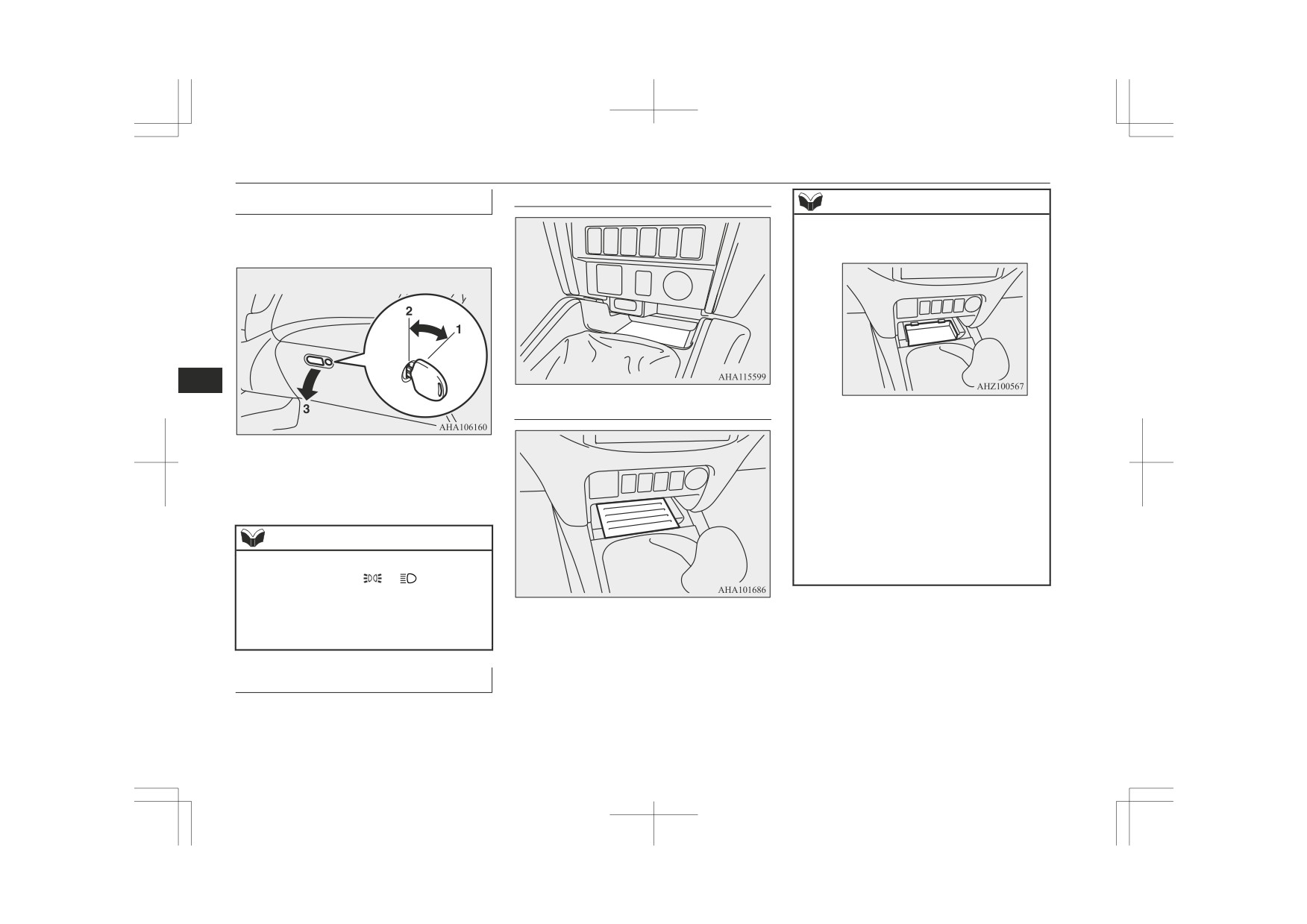
Centre console under tray
The centre console under tray is on the floor
console part.
7-102
For pleasant driving
Storage spaces
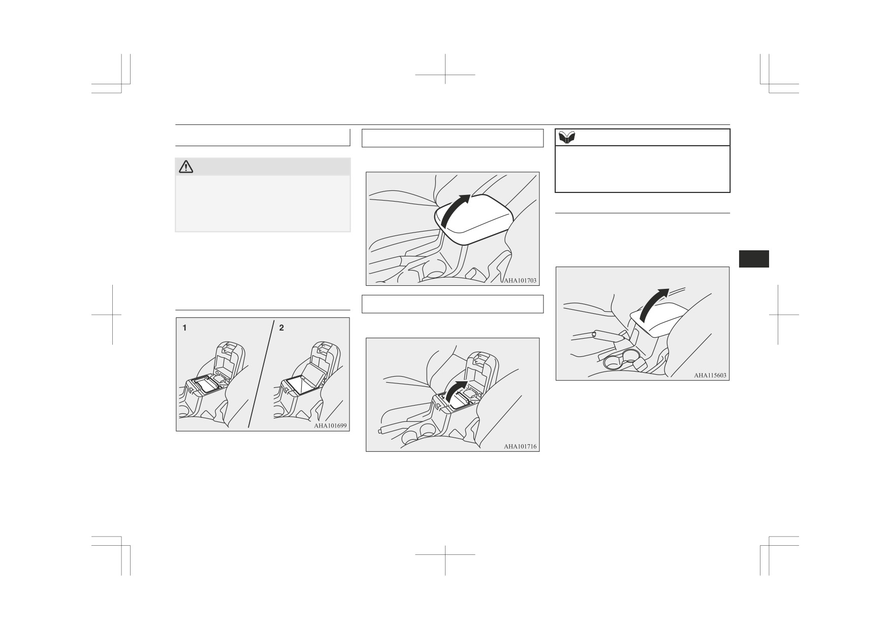
Floor console box
Upper box
NOTE
To open the upper box, raise the lid.
z When opening or closing the lid, be careful
not to trap hands.
CAUTION
z
The upper box can be removed and use as a
z Keep the lid of floor console box closed
box.
while driving the vehicle.
If the brakes are applied suddenly, hands or
Type 2
fingers may be trapped because of closing
the lid.
To open the console box, raise the lid.
The floor console box can also be used as an
Upper and lower boxes are located inside the
armrest.
floor console box.
7
The floor console box can also be used as an
armrest.
Type 1
Lower box
To open the lower box, raise the upper box.
1- Upper box
2- Lower box
For pleasant driving
7-103

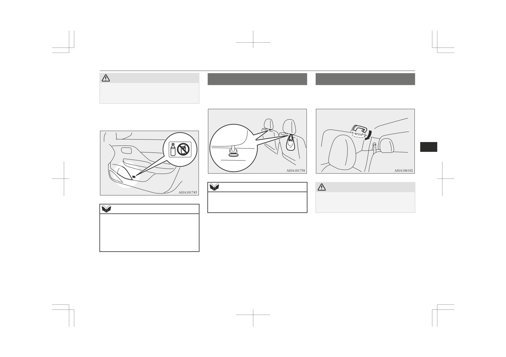
Cup holder
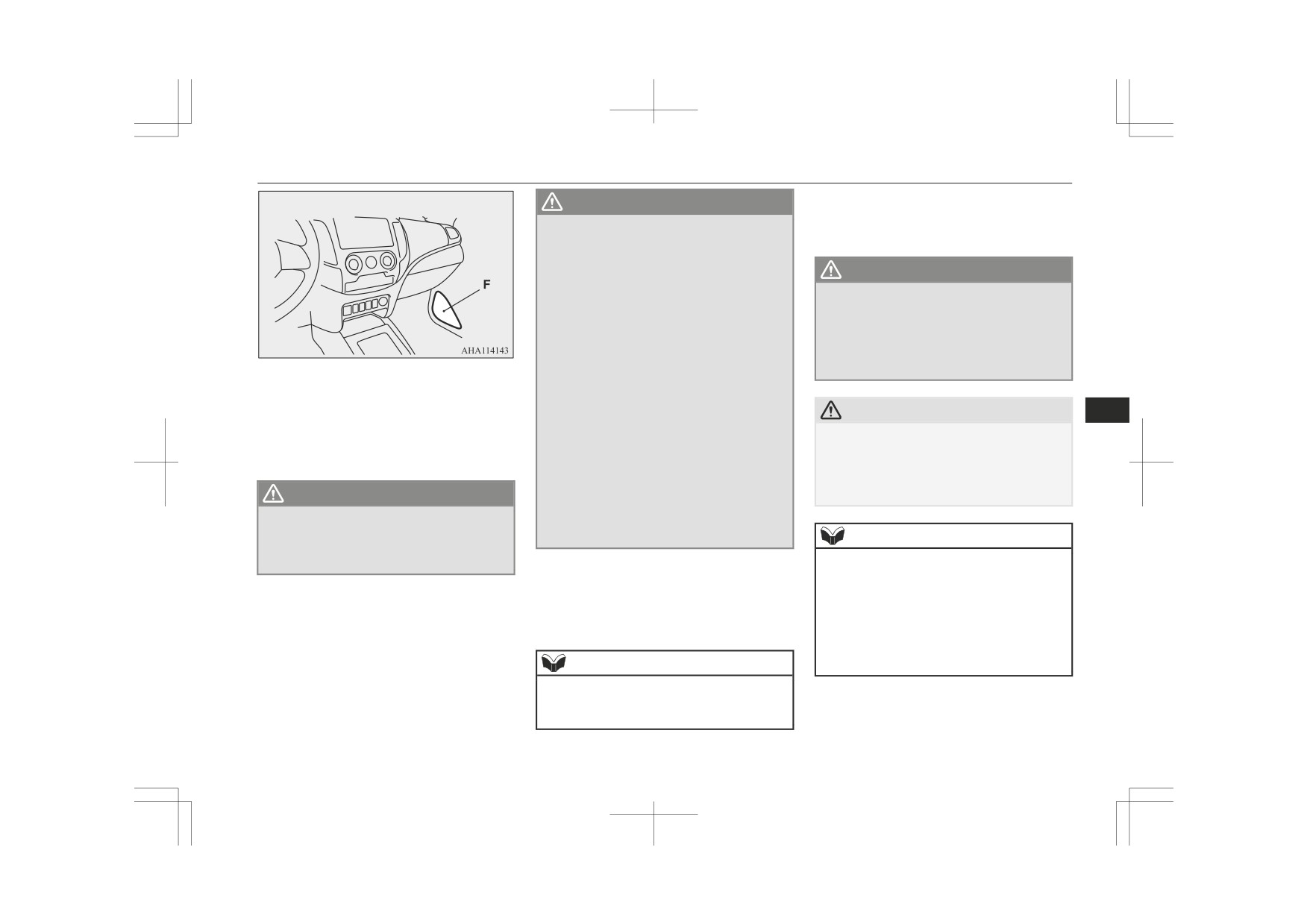
Sunglasses holder*
Cup holder
For the rear seat
To open, push the lid.
In order to use the cup holder, allow the arm-
WARNING
rest to drop down.
z Do not spray water or spill beverages in-
side the vehicle. If the switches, wires or
electrical components become wet, they
could malfunction or cause a vehicle fire.
If you accidentally spill a beverage, wipe
up as much liquid as possible and imme-
diately consult a MITSUBISHI MOTORS
Authorized Service Point.
7
CAUTION
Do not drink beverages while driving. This
z
is distracting and could cause an accident.
CAUTION
Bottle holder
z
The holder should not be used to store any-
For the front seat
thing heavier than sunglasses. These objects
could drop out.
WARNING
The cup holder is located between the front
seats.
z Do not spray water or spill beverages in-
NOTE
side the vehicle. If the switches, wires or
electrical components become wet, they
z
The holder may not be able to accomodate
could malfunction or cause a vehicle fire.
every possible size and shape of sunglasses;
If you accidentally spill a beverage, wipe
it is advisable to check compatibility before
up as much liquid as possible and imme-
use.
diately consult a MITSUBISHI MOTORS
Authorized Service Point.
CAUTION
z Do not drink beverages while driving. This
is distracting and could cause an accident.
7-104
For pleasant driving
Convenient hook
CAUTION
Convenient hook
Assist grip
z Drinks could be spilled by the vibration and
Light items of luggage can be hung from the
These grips are to support the body by hand
jolts while driving. If the spilt drink is very
hot, you could be burnt.
hook.
while seated in the vehicle.
The bottle holders are provided at both sides
of front and rear doors.
7
NOTE
CAUTION
z Do not hang heavy luggage (more than ap-
z Do not use the assist grips when getting into
proximately 4 kg) on the hook.
or out of the vehicle. The assist grips could
Doing so could cause damage to the hook.
detach causing you to fall.
NOTE
z Do not store cup or drink can in the bottle
holder.
z Tightly close the cap on drink bottles before
storing them.
z Some bottles may be too big or the wrong
shape to fit in the holder.
For pleasant driving
7-105

Coat hook*
A band for securing a warning triangle is in-
Coat hook*
First-aid kit and warning
stalled left under the rear seat.
triangle securing band(s)
There is a coat hook on the rear seat assist
grip.
A first-aid kit and a warning triangle can be
secured with the band installed in the illustra-
ted position.
Club cab
A band for securing a first-aid kit is installed
under the floor on the left-hand side of the
7
rear seat.
Double cab
The wall behind the seat is provided with a
WARNING
band for securing a first-aid kit and a warning
triangle.
z Do not put a hanger or any heavy or poin-
ted object on the coat hook. If the curtain
airbag was activated, any such item could
be propelled away with great force and
could prevent the curtain airbag from in-
flating correctly. Hang clothes directly on
the coat hook (without using a hanger).
Make sure there are no heavy or sharp
objects in the pockets of clothes that you
hang on the coat hook.
7-106
For pleasant driving
For emergencies
ERA-GLONASS*
8-02
If the vehicle breaks down
8-07
If the operation mode cannot be changed to OFF (vehicles
equipped with the keyless operation system)
8-07
Emergency starting
8-07
Engine overheating
8-09
Bleeding the fuel system
8-11
Removal of water from the fuel filter
8-11
8
Tools, jack and jack handle
8-12
How to change a tyre
8-16
Towing
8-23
Operation under adverse driving conditions
8-27

ERA-GLONASS*
ERA-GLONASS*
WARNING
Flow of the emergency call
•
When the vehicle is in a place where ra-
ERA-GLONASS is a system designed to re-
dio waves cannot be transmitted and
duce the severity of accidents. The location
received. (for example, indoor, a base-
and vehicle information is transmitted from
ment parking area, mountainous area,
the system to the emergency call centre in
inside a tunnel, etc.)
case of an accident or sudden illness, and the
• When the line to the emergency call
centre is busy and the call cannot be
emergency call centre arranges for despatch
connected to the emergency call centre.
of emergency vehicles as required.
NOTE
WARNING
z
This system reports to the emergency call
z
In countries or areas where there is no
8
centre, but does not directly arrange an
available emergency call centre of the
emergency vehicle or pass to the road serv-
ERA-GLONASS, or where the radio wave
ice.
of the emergency call cannot be transmit-
z
This system helps to make an emergency
ted or received normally, the system does
call for a traffic accident or sudden illness,
not operate. In this case, directly arrange
but does not have a function to protect the
an emergency vehicle or road service with
occupants.
a cellular phone, etc.
z
If an emergency occurs and you notice a
fuel smell or bad smell, do not stay inside
the vehicle and escape to a safe place im-
mediately.
z
While waiting for the rescue after the
emergency call, take action to prevent sec-
ondary accidents such as a rear end colli-
sion with the following vehicle, and escape
to a safe place.
z
In the following cases, directly arrange an
emergency vehicle or road service with a
cellular phone, etc.
• When the system does not operate by
failing because of collision, etc.
8-02
For emergencies
ERA-GLONASS*
[Manual Report]
WARNING
When you open the cover (C) and press
z
If the red lamp and/or the green lamp do
the SOS switch (D).
not illuminate after setting the ignition
switch or the operation mode to “ON”,
there is a possible failure in the system.
WARNING
Have the system inspected by a
z
Before pressing the SOS switch, stop the
MITSUBISHI MOTORS Authorized
vehicle in a safe place. If you operate it
Service Point immediately.
while driving, your attention to the sur-
z
If the red lamp remains illuminated or il-
rounding circumstances becomes insuffi-
luminates again after approximately 20
cient, enough to cause an unexpected acci-
seconds has elapsed after setting the igni-
dent.
A- Red lamp
tion switch or the operation mode to
B- Green lamp
“ON”, there is a possible failure in the
C- Cover
system or the battery for exclusive use of
CAUTION
8
D- SOS switch
the ERA-GLONASS may be exhausted.
The battery life is approximately 3 years.
Do not open the cover except when you
E- Microphone
z
Have the system inspected or replace the
press the SOS switch. You may press the
F- Door speaker (only front passenger side)
battery by a MITSUBISHI MOTORS Au-
SOS switch by mistake. In addition, if the
thorized Service Point immediately.
cover is opened while driving, the cover can
When the system is not in the standby
cause injury in case of an emergency.
WARNING
z
state, the system does not operate. When
z
Do not remove or install the above parts.
you drive, make sure to check that the
This can cause failure of contact or equip-
system is in the standby state.
NOTE
ment, and the system may not operate
normally.
z
Before the manual report gets connected, it
2. The system operates as follows.
can be cancelled by long pressing the SOS
[Automatic Report]
button again for more than 2 seconds.
1. After setting the ignition switch or the
When the vehicle receives an impact
z
Do not press the SOS switch except in case
operation mode to “ON”, the red lamp
an emergency such as an accident or sudden
above a certain level.
(A) and the green lamp (B) illuminate
illness. When an emergency vehicle, etc. is
for approximately 10 seconds. When ap-
despatched for mischief, the applicable cost
proximately 10 seconds have elapsed af-
NOTE
may be charged.
ter the lamps extinguish, the system is in
Depending on the level of impact or the an-
z
the standby state.
gle of the collision, the system may not oper-
3. The green lamp blinks and the system
ate.
calls the emergency call centre.
For emergencies
8-03

ERA-GLONASS*
and the buzzer sounds once, a conversa-
WARNING
NOTE
tion with an operator of the emergency
z
If the red lamp illuminates as follows, di-
z If the vehicle side microphone (E) and/or the
call centre is available.
rectly arrange an emergency vehicle or
speakers fail, you cannot talk with the opera-
road service with a cellular phone, etc.
tor of the emergency call centre.
• When the red lamp remains illumina-
WARNING
z A call cannot be disconnected from the vehi-
ted. (There is a possible failure in the
cle side.
system.)
z Do not replace the speakers. If they are
replaced, the buzzer sound or the voice of
• When the red lamp illuminates for 60
the operator at the emergency call centre
6. The emergency call centre arranges for
seconds. (The vehicle may be in a place
may not be audible. If the speakers need
despatch of the emergency vehicle as re-
where radio waves cannot be transmit-
to be replaced due to a failure etc., we rec-
quired.
ted and received.)
ommend you to consult a MITSUBISHI
MOTORS Authorized Service Point.
Indicator list
4. The green lamp blinks slowly, and the
z An error may occur between the actual
8
location and vehicle information is trans-
report point and the point reported to the
emergency call centre. Mutually confirm
mitted to the emergency call centre.
the report point and the object through
5. When the green lamp changes from a
the phone call with the operator of the
blinking state to an illumination state
emergency call centre.
Indication lamp
Situation
Cause
Solution
Buzzer Sound
Red lamp
Green lamp
Wait for a while.
The indication lamps extinguish
when the system check is com-
plete.
When setting the igni-
Illuminates (for
Illuminates (for
If the red lamp and/or the green
The system check is
tion switch or the op-
approximately 10
approximately 10
lamp do(es) not illuminate, there
No sound
in progress.
eration mode to “ON”
seconds)
seconds)
is a possible failure in the system.
In this case, immediately have the
system inspected at a
MITSUBISHI MOTORS Author-
ized Service Point.
8-04
For emergencies

ERA-GLONASS*
Indication lamp
Situation
Cause
Solution
Buzzer Sound
Red lamp
Green lamp
The system works
After approximately 20
Extinguishes
Extinguishes
−
No sound
normally.
seconds after setting
There is a possible
the ignition switch or
Immediately have the system in-
failure in the system
the operation mode to
Illuminates
Extinguishes
spected at a MITSUBISHI MO-
3 times
or the battery may be
“ON”
TORS Authorized Service Point.
exhausted.
The system calls the
Blinks (at a 0.5-
Extinguishes
emergency call cen-
−
No sound
second interval)
tre.
8
The system transmits
the location and vehi-
Blinks (at a 2-sec-
Extinguishes
cle information to the
−
No sound
ond interval)
emergency call cen-
While the emergency
tre.
call is activated
Mutually confirm the details of
the emergency call with the oper-
A conversation with
ator of the emergency call centre.
an operator of the
If the green lamp does not extin-
Extinguishes
Illuminates
once
emergency call centre
guish even after the emergency
is available.
call ends, have the system inspec-
ted at a MITSUBISHI MOTORS
Authorized Service Point.
Make an emergency call again, or
Illuminates (for
When the emergency
The emergency call
directly arrange an emergency ve-
approximately 60
Extinguishes
3 times
call failed
failed.
hicle or road service with the
seconds)
nearest public telephone, etc.
For emergencies
8-05
ERA-GLONASS*
Test Mode
NOTE
NOTE
z
If the buzzer does not sound, repeat the
z If you drive a certain distance in the test
The system can be checked if it is in the nor-
process from Step 1.
mode, the test mode ends.
mal standby state by the following process.
Before operation, stop the vehicle in a safe
6. Approximately
60 seconds later, the
Report test to the emergency
place, with good visibility, where radio
green lamp blinks. If you press the SOS
call centre
waves can be transmitted and received.
switch within
20 seconds, the mode
1. The green lamp illuminates, and the re-
changes to the test mode.
port test to the emergency call centre is
NOTE
started.
z The test emergency call must be carried out
NOTE
by qualified personnel only.
Therefore, if you want to check the system,
z
When the red lamp blinks instead of the
NOTE
please consult a MITSUBISHI MOTORS
green lamp, move the vehicle in a safe place,
8
z If the red lamp illuminates for approximately
Authorized Service Point.
with good visibility, where radio waves can
60 seconds, the vehicle is in a place where
be transmitted and received, then repeat the
radio waves cannot be transmitted and re-
process from Step 1.
Change to Test Mode
ceived. Therefore you cannot report to the
emergency call centre.
1. When the ignition switch or the opera-
7. Within approximately 20 seconds after
tion mode is set to “OFF”, set the igni-
the mode has changed to the test mode,
tion switch or the operation mode to
2. When the green lamp extinguishes, the
press the SOS switch for one of the fol-
“ON” while pressing the SOS switch.
test mode is completed.
lowing periods to select the desired test
2. After setting the ignition switch or the
type.
Test of the ERA-GLONASS sys-
operation mode to “ON”, perform Steps
z
10 seconds or more: Report test to the
tem equipment of the vehicle
3 and 4 within 10 seconds.
emergency call centre
3. Release your finger from the SOS
1. After the buzzer sounds once, press the
z Less than
10 seconds: Test of the
switch.
SOS switch.
ERA-GLONASS system equipment of
4. Press the SOS switch 3 or more times.
[Lamp Check]
the vehicle
5. After approximately
10 seconds from
When the buzzer sounds once and both
Step 2, the red lamp and the green lamp
the red and green lamp illuminate alter-
extinguish. After that, the buzzer sounds
NOTE
nately, they are working normally.
3 times.
z If you do not press the SOS switch within
approximately
20 seconds, the test mode
ends.
8-06
For emergencies
If the vehicle breaks down
2. When the lamps are normal, press the
6. When the green lamp extinguishes, the
1. Move the selector lever to the
“P”
SOS switch. When the lamps do not illu-
test mode is completed.
(PARK) position, and then change the
minate normally, wait for approximately
operation mode to OFF. (For vehicles
20 seconds.
with A/T)
If the vehicle breaks down
[Speaker Check]
2. One of the other causes could be low
When the buzzer sounds twice and con-
battery voltage. If this occurs, the key-
If the vehicle breaks down on the road, move
tinues sounding, they are working nor-
less entry system, keyless operation
it to the shoulder and use the hazard warning
mally.
function and steering lock will also not
flashers and/or the warning triangle etc.
3. When the speakers are normal, press the
operate. Contact a MITSUBISHI
Refer to “Hazard warning flasher switch” on
SOS switch. When the buzzer does not
MOTORS Authorized Service Point.
page 5-62.
sound normally, wait for approximately
20 seconds.
If the engine stops/fails
Emergency starting
[Microphone Check]
After the buzzer sounds
3 times, say
8
Vehicle operation and control are affected if
If the engine cannot be started because the
something towards the microphone.
the engine stops. Before moving the vehicle
battery is weak or dead, the battery from an-
If your voice sounds from the speakers,
to a safe area, be aware of the following:
other vehicle can be used with jumper cables
they are working normally.
z The brake booster becomes inoperative
to start the engine.
4. When the microphone is normal, press
and the pedal effort will increase. Press
the SOS switch. When it does not oper-
down the brake pedal harder than usual.
ate normally, wait for approximately 20
WARNING
z Since the power steering system is no
seconds.
longer operative, the steering wheel feels
z To start the engine using jumper cables
5. If all check results are normal, the green
heavy when turning it.
connected to another vehicle, perform the
lamp illuminates
(for approximately
5
correct procedures according to the in-
seconds) and the buzzer sounds once.
struction below. Incorrect procedures
If the operation mode
could result in a fire or explosion or dam-
age to the vehicles.
cannot be changed to OFF
WARNING
z Keep sparks, cigarettes and flames away
(vehicles equipped with the
from the battery because the battery may
z
If any of the check results are not normal,
produce an explosion.
the red lamp illuminates
(for approxi-
keyless operation system)
mately 5 seconds) and the buzzer sounds 3
times. In this case, there is a possible fail-
If the operation mode cannot be changed to
ure in the system. Have the system inspec-
OFF, perform the following procedure.
ted by a MITSUBISHI MOTORS Author-
ized Service Point immediately.
For emergencies
8-07

Emergency starting
4. Make sure battery electrolyte is at the
CAUTION
NOTE
proper level.
z
Do not attempt to start the engine by pulling
z
Open the terminal cover before connecting
Refer to “Battery” on page 10-09.
or pushing the vehicle.
the jumper cable to the positive (+) terminal
It could damage your vehicle.
of the battery.
z
Check the other vehicle. It must have a 12-
WARNING
(Refer to “Battery” on page 10-09.)
volt battery.
z
If electrolyte fluid is not visible, or ap-
If the other system isn’t 12-volt, shorting can
pears to be frozen, Do Not Attempt Jump
damage both vehicles.
Starting!
z
Use the proper cables suitable for the battery
A battery might rupture or explode if the
size to prevent overheating of the cables.
temperature is below the freezing point or
z
Check the jumper cables for damage and
if it is not filled to the proper level.
corrosion before use.
z
Electrolyte is corrosive diluted sulphuric
z
Always wear protective eye goggles when
acid.
working near the battery.
8
If electrolyte
(battery acid) comes into
z
Keep the battery out of the reach of children.
contact with your hands, eyes, clothes and
the painted surface of your vehicle, it
should be thoroughly flushed with water.
1. Get the vehicles close enough so the
If electrolyte gets in your eyes, flush them
jumper cables can reach, but be sure the
with water immediately and thoroughly,
vehicles aren’t touching each other.
and get prompt medical attention.
WARNING
2. Turn off all lamps, heater and other elec-
trical loads.
z
Make sure that the connection is made
5. Connect one end of one jumper cable
3. Set the parking brake firmly on each ve-
to the appointed position (shown in the il-
to the positive (+) terminal of the dis-
hicle. Put an automatic transmission in
lustration). If the connection is made di-
charged battery (A), and the other end
rectly to the negative (−) side of the bat-
“P” (PARK) or a manual transmission in
to the positive (+) terminal of the booster
tery, the inflammable gases generated
“N” (Neutral). Stop the engine.
battery (B).
from the battery might catch fire and ex-
plode.
Connect one end of the other jumper ca-
WARNING
z
When connecting the jumper cables, do
ble
to the negative (−) terminal of the
not connect the positive (+) cable to the
z
Turn off the ignition on both vehicles be-
booster battery (B), and the other end
negative (−) terminal. Otherwise sparks
forehand. Make sure that the cables or
to the engine block of the vehicle with
might cause explosion of the battery.
your clothes cannot be caught by the fan
the discharged battery at the point far-
or drive belt. Personal injury could result.
thest from the battery.
8-08
For emergencies

Engine overheating
CAUTION
NOTE
NOTE
z
Take care not to get the jumper cable caught
z If the vehicle is put in motion without fully
z
For vehicles equipped with the Auto Stop &
in the cooling fan or other rotating part in
charging the battery, it might cause the loss
Go (AS&G) system, press the “Auto Stop &
the engine compartment.
of the smooth engine operation and the anti-
Go (AS&G) OFF” switch to deactivate the
lock brake warning lamp to illuminate.
Auto Stop & Go (AS&G) system before
Refer to “Anti-lock brake system (ABS)” on
stopping the vehicle.
6. Start the engine in the vehicle which has
page 6-73.
Refer to “To deactivate” on page 6-28.
the booster battery, let the engine idle a
few minutes, then start the engine in the
[If steam is coming from the engine
vehicle with the discharged battery.
Engine overheating
compartment]
Stop the engine, and when the steam
When the engine is overheating, the warning
CAUTION
stops, raise the bonnet to ventilate the
will be displayed in the instrument cluster as
Keep the engine of the vehicle giving assis-
engine compartment. Restart the engine.
z
follows.
8
tance running.
z The information screen in the multi in-
formation display will be interrupted and
WARNING
the engine coolant temperature warning
NOTE
Do not open the bonnet while steam is
z
display will appear. Also “
” will blink.
coming from the engine compartment. It
z
For vehicles equipped with the Auto Stop &
(Colour liquid crystal display type)
could cause steam or hot water to spurt
Go (AS&G) system, press the “Auto Stop &
z
“
” will blink.
(Mono-colour liquid
out, causing burns. Hot water could spurt
Go (AS&G) OFF” switch to deactivate the
crystal display type)
out even when there is no steam coming
Auto Stop & Go (AS&G) system and pre-
out, and some parts will be very hot. Be
vent the engine from automatically stopping
very careful when opening the bonnet.
before the battery is sufficiently charged.
If this occurs, take the following corrective
z
Be careful of hot steam, which could be
Refer to “To deactivate” on page 6-28.
measures:
blowing off the reserve tank cap.
1. Stop the vehicle in a safe place.
7. After the engine is started, disconnect
2. Check whether steam is coming from the
the cables in the reverse order and keep
engine compartment.
the engine running for several minutes.
[If steam does not come from the engine
compartment]
With the engine still running, raise the
bonnet to ventilate the engine compart-
ment.
For emergencies
8-09