Mitsubishi Outlander XL. Manual - part 932
STEP 12. Recheck for diagnostic trouble code.
ZC501967
AC404789
ZC5019680000
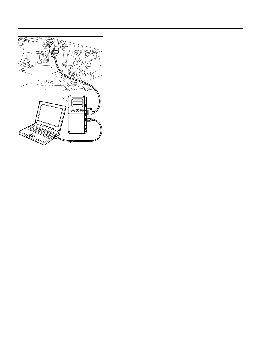
MB991824
MB991827
MB991910
Data link
connector
Check again if the DTC is set.
(1)
Erase the DTC.
(2)
Turn the ignition switch to the "ON" position.
(3)
Check if the DTC is set.
(4)
Turn the ignition switch to the "LOCK" (OFF) position.
Q:Is DTC B210D set?
YES:
Return to Step 1.
NO:
The procedure is complete.
DTC B212C: Open Circuit to IG1 Power Supply (Fuse No.12 Circuit)
SUPPLEMENTAL RESTRAINT SYSTEM (SRS)
52B-259
SRS AIR BAG DIAGNOSIS