Mitsubishi Outlander XL. Manual - part 930
ZC6018230000
Seat belt
pre-tensioner
Floor wiring harness side
connector (2-pin, black)
Locking
button
Flat-tipped
screwdriver
(2)
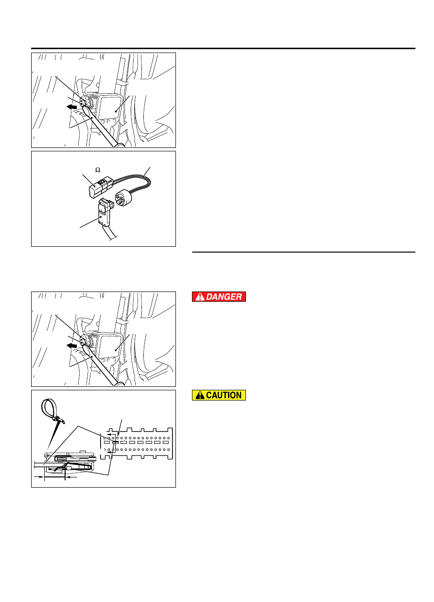
Disconnect passenger's seat belt pre-tensioner connector
D-130. Use a flat-tipped screwdriver to unlock the locking
button at the harness side connector by withdrawing it toward
you in two stages, and then disconnect the connector.
ZC600214
Harness side
connector
MB991865
(Dummy resistor: 3
)
MB991884
(Resistor harness)
0000
(3)
Connect special tool MB991865 to special tool MB991884.
(4)
Connect special tool MB991884 to the D-130 harness side
connector.
(5)
Connect the negative battery terminal.
(6)
Erase diagnostic trouble code memory, and then check the
diagnostic trouble code.
Q:Is DTC B1C4A set?
YES:
Go to Step 5.
NO:
Replace the passenger's seat belt with pre-tensioner
(Refer to P.52B-345). Then go to Step 7.
STEP 5. Check the passenger's seat belt pre-tensioner
circuit. Measure the resistance at the SRS-ECU connector
C-27.
(1)
Disconnect SRS-ECU connector C-27.
ZC6018230000
Seat belt
pre-tensioner
Floor wiring harness side
connector (2-pin, black)
Locking
button
Flat-tipped
screwdriver
To prevent the seat belt pre-tensioner from deploying
unintentionally, disconnect the passenger’s seat belt pre-
tensioner connector D-130 to short the squib circuit.
(2)
Disconnect passenger's seat belt pre-tensioner connector
D-130. Use a flat-tipped screwdriver to unlock the locking
button at the harness side connector by withdrawing it toward
you in two stages, and then disconnect the connector.
ZC6021620006
A
A
C-27 Harness side
connector (front view)
Section
A - A
Cable tie
Short spring
4 mm or more
Terminal
Insert an insulator such as a cable tie to a depth of 4mm
(0.16 inch) or more, otherwise the short spring will not be
released.
(3)
Insert a cable tie [3 mm (0.12 inch) wide, 0.5 mm (0.02 inch)
thick] between terminals 43, 44 and the short spring to
release the short spring.
SUPPLEMENTAL RESTRAINT SYSTEM (SRS)
52B-251
SRS AIR BAG DIAGNOSIS