Mitsubishi Outlander XL. Manual - part 881


  Index      Mitsubishi     Mitsubishi Outlander XL - service repair manual 2007 year


Search            copyright infringement  


Content   ..  879  880  881  882   ..


Mitsubishi Outlander XL. Manual - part 881


If DTC B1B01 <1st squib> or B1B05 <2nd squib>
is set in the SRS-ECU, always diagnose the CAN
main bus line.

CIRCUIT OPERATION

The SRS-ECU judges how severe a collision is by
detecting signals from the front impact sensors and
the front air bag analog G-sensor. If the impact is
over a predetermined level, the SRS-ECU sends an
ignition signal. At this time, if the front air bag safing
G-sensor is on, the SRS air bag will inflate.

The ignition signal is input to the air bag module via
the clock spring to inflate the air bag.

DTC SET CONDITIONS
This  DTC  is  set  if  there  is  abnormal  resistance
between  the  input  terminals  of  the  driver's  air  bag
module (squib).

TROUBLESHOOTING HINTS

Malfunction of the clock spring

Damaged harness wires and connectors

Short  to  the  power  supply  in  the  driver's  air  bag
module (squib) harness

Malfunction of the SRS-ECU

DIAGNOSIS

Required Special Tools:

MB991958: Scan Tool (M.U.T.-III Sub Assembly)

MB991824: Vehicle Communication Interface (V.C.I.)

MB991827: M.U.T.-III USB Cable

MB991910:  M.U.T.-III  Main  Harness  A  (Vehicles  with
CAN Communication System)

MB991865: Dummy resistor

MB991866: Resister harness

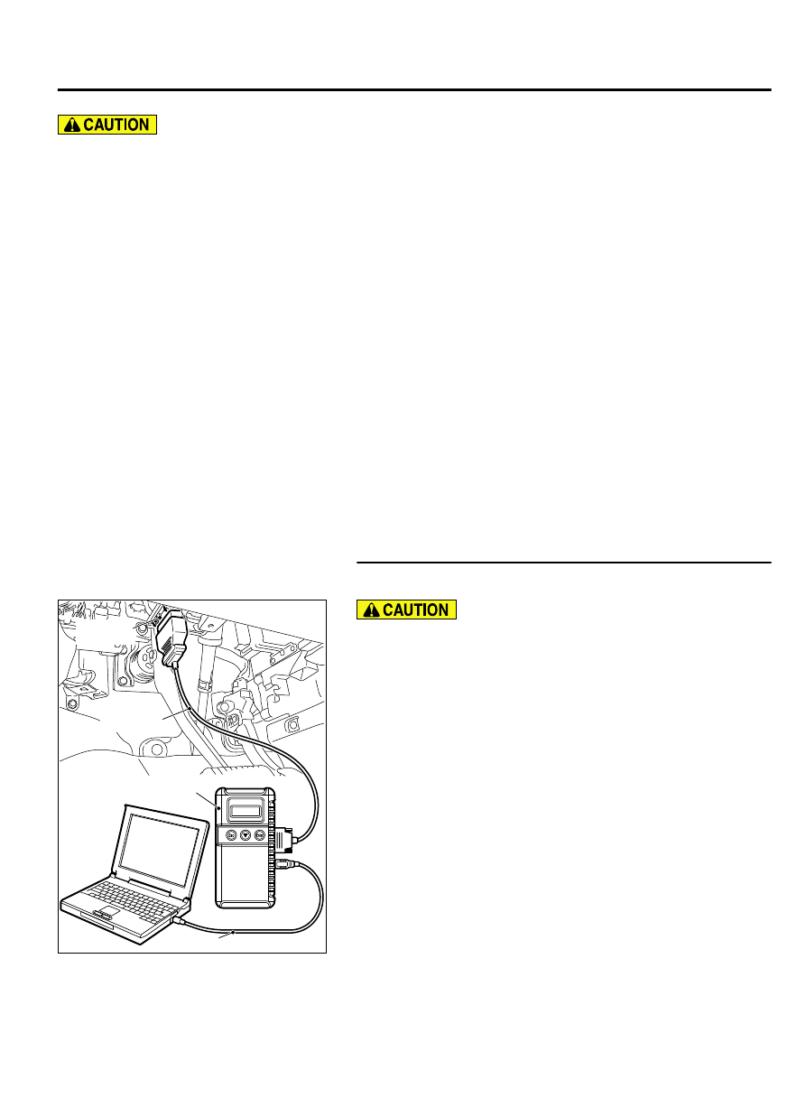
STEP 1. Using scan tool MB991958, diagnose the CAN bus
line.

ZC501967

AC404789

ZC5019680000

MB991824

MB991827

MB991910

Data link

connector

To prevent damage to scan tool MB991958, always turn the
ignition  switch  to  the  "LOCK"  (OFF)  position  before
connecting or disconnecting scan tool MB991958.

(1)

Connect scan tool MB991958. Refer to "How to connect the
scan tool P.52B-31."

(2)

Turn the ignition switch to the "ON" position.

(3)

Diagnose the CAN bus line.

(4)

Turn the ignition switch to the "LOCK" (OFF) position.

Q:Is the CAN bus line found to be normal?

YES:

 Go to Step 2.

NO:

 Repair the CAN bus line (Refer to GROUP 54D,

Diagnosis P.54D-17).

SUPPLEMENTAL RESTRAINT SYSTEM (SRS)

52B-55

SRS AIR BAG DIAGNOSIS

STEP 2. Recheck for diagnostic trouble code.

ZC501967

AC404789

ZC5019680000

MB991824

MB991827

MB991910

Data link

connector

Check again if the DTC is set.

(1)

Erase the DTC.

(2)

Turn the ignition switch to the "ON" position.

(3)

Check if the DTC is set.

(4)

Turn the ignition switch to the "LOCK" (OFF) position.

Q:Is the DTC set?

YES:

 Go to Step 3.

NO:

 There is an intermittent malfunction such as poor

engaged connector(s) or open circuit (Refer to GROUP 00,
How to Cope with Intermittent Malfunction P.00-15).

STEP 3. Check the driver's air bag module. (Using scan tool
MB991958, read the diagnostic trouble code.)

(1)

Disconnect the negative battery terminal.

(2)

Slide  the  outer  housing  of  the  driver’  s  air  bag  module
connector  C-205  in  the  arrow  direction  shown,  and
disconnect the connector.

ZC600213

Outer housing of the driver's air bag  
module connector 

0001

ZC600207

C-205 Air bag  
module connector

MB991866 (Resistor 
 harness)

MB991865 (Dummy  
resistor : 3 


)

0000

(3)

Connect special tool MB991865 to special tool MB991866.

Do not insert a probe into the terminal from its front side
directly,  as  the  connector  contact  pressure  may  be
weakened.

(4)

Insert special tool MB991866 into clock spring side air bag
module connector C-205 (terminal No.1 and 2 <1st squib> or
terminal No.3 and 4 <2nd squib>) by backprobing.

(5)

Connect the negative battery terminal.

Always DTC B1B06 is set when checking DTC B1B01. This
is  because  the  second  side  terminal  is  isolated  when
checking  it.  DTC  B1B06  is  set  but  this  is  not  a  fault.  In
addition,  always  DTC  B1B02  is  set  when  checking  DTC
B1B05 because the first side terminal is isolated.

(6)

Erase the diagnostic trouble code memory, and check the
diagnostic trouble code.

Q:Is the checked DTC set?

YES:

 Go to Step 4.

NO:

 Replace the driver’s air bag module. (Refer to P.

52B-329). Then go to Step 7.

52B-56

SUPPLEMENTAL RESTRAINT SYSTEM (SRS)

SRS AIR BAG DIAGNOSIS

STEP 4. Check the clock spring. (Using scan tool MB991958,
read the diagnostic trouble code.)

(1)

Disconnect the negative battery terminal.

(2)

Disconnect the clock spring connector C-207.

ZC600208

C-207 Harnnes side 
connector

MB991866 (Resistor 
 harness)

MB991865 (Dummy  
resistor : 3 


)

0000

(3)

Connect special tool MB991865 to special tool MB991866.

Do not insert a test probe into the terminal from its front side
directly,  as  the  connector  contact  pressure  may  be
weakened.

(4)

Insert special tool MB991866 into clock spring harness side
connector C-207 (terminal No.3 and 4 <1st squib> or terminal
No. 2 and 1 <2nd squib>) by backprobing.

(5)

Connect the negative battery terminal.

Always DTC B1B06 is set when checking DTC B1B01. This
is  because  the  second  side  terminal  is  isolated  when
checking  it.  DTC  B1B06  is  set  but  this  is  not  a  fault.  In
addition,  always  DTC  B1B02  is  set  when  checking  DTC
B1B05 because the first side terminal is isolated.

(6)

Erase the diagnostic trouble code memory, and check the
diagnostic trouble code.

Q:Is the checked DTC set?

YES:

 Go to Step 5.

NO:

 Replace the clock spring (Refer to P.52B-329). Then

go to Step 7.

STEP 5. Check the driver’s air bag module circuit. Measure
the voltage at the SRS-ECU connector C-28.

(1)

Disconnect SRS-ECU connector C-28.

ZC600210

A

Lock lever

0000

(2)

While  pushing  the  part  "A"  indicated  in  the  figure  of  the
harness side connector, turn the lock lever to the direction of
the arrow to release the lock lever, and disconnect the C-28
SRS-ECU connector.

To  prevent  the  air  bag  from  deploying  unintentionally,
disconnect the clock spring connector C-207 to short the
squib circuit.

(3)

Disconnect the clock spring connector C-207.

(4)

Turn the ignition switch to the "ON" position.

ZC5007950008

C-28 Harness side  
connector (front view)

<1st squib>

(5)

Measure the voltage between C-28 harness side connector
terminals 5 and 6 <1st squib> or 9 and 10 <2nd squib> and
body ground.
Voltage should measure 0 volt.

Q:Is the measured voltage within the specified range?

YES:

 Erase the diagnostic trouble code memory, and check

the diagnostic trouble code. If DTC B1B01 <1st squib> or
B1B05 <2nd squib> sets, replace the SRS-ECU. (Refer to P.
52B-326). Then go to Step 7.

NO:

 Go to Step 6.

SUPPLEMENTAL RESTRAINT SYSTEM (SRS)

52B-57

SRS AIR BAG DIAGNOSIS

ZC5007950009

C-28 Harness side  
connector (front view)

<2nd squib>

STEP 6. Check the harness for short circuit to power supply
between SRS-ECU connector C-28 (terminal No.5 and 6 <1st
squib> or terminal No.9 and 10 <2nd squib>) and clock
spring connector C-207 (terminal No.4 and 3 <1st squib> or
terminal No. 1 and 2 <2nd squib>).

Q:Are harness wires between the SRS-ECU connector C-28

(terminal No.5 and 6 <1st squib> or terminal No.9 and 10

<2nd squib>) and clock spring connector C-207 (terminal

No.4  and  3  <1st  squib>  or  terminal  No.  1  and  2  <2nd

squib>) in good condition?

YES:

 Go to Step 7.

NO:

 Replace the harness wires between SRS-ECU connector

C-28 and clock spring connector C-207. Then go to Step 7.

STEP 7. Recheck for diagnostic trouble code.

ZC501967

AC404789

ZC5019680000

MB991824

MB991827

MB991910

Data link

connector

Check again if the DTC is set.

(1)

Erase the DTC.

(2)

Turn the ignition switch to the "ON" position.

(3)

Check if the DTC is set.

(4)

Turn the ignition switch to the "LOCK" (OFF) position.

Q:Is DTC B1B01 <1st squib> or B1B05 <2nd squib> set?

YES:

 Return to Step 1.

NO:

 The procedure is complete.

DTC B1B02: Driver's Air Bag Module (1st squib) System (Squib Circuit Open)

52B-58

SUPPLEMENTAL RESTRAINT SYSTEM (SRS)

SRS AIR BAG DIAGNOSIS


Content   ..  879  880  881  882   ..