Mitsubishi Outlander XL. Manual - part 880
(6)
Erase the diagnostic trouble code memory, and check the
diagnostic trouble code.
Q:Is the checked DTC set?
YES:
Go to Step 4.
NO:
Replace the driver's air bag module (Refer to P.
STEP 4. Check the clock spring. (Using scan tool MB991958,
read the diagnostic trouble code.)
(1)
Disconnect the negative battery terminal.
(2)
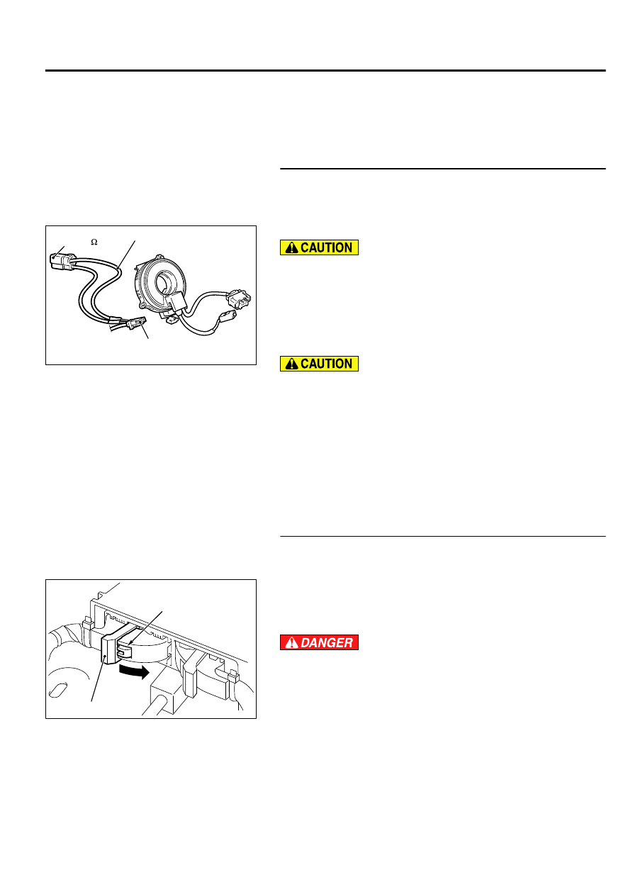
Disconnect the clock spring connector C-207.
ZC600208
C-207 Harnnes side
connector
MB991866 (Resistor
harness)
MB991865 (Dummy
resistor : 3
)
0000
(3)
Connect special tool MB991865 to special tool MB991866.
Do not insert a test probe into the terminal from its front side
directly, as the connector contact pressure may be
weakened.
(4)
Insert special tool MB991866 into clock spring harness side
connector C-207 (terminal No. 3 and 4 <1st squib> or
terminal No. 1 and 2 <2nd squib>) by backprobing.
(5)
Connect the negative battery terminal.
Always DTC B1B06 is set when checking DTC B1B00. This
is because the second side terminal is isolated when
checking it, DTC B1B06 is set but this is not a fault. In
addition, always DTC B1B02 is set when checking DTC
B1B04 because the first side terminal is isolated.
(6)
Erase the diagnostic trouble code memory, and check the
diagnostic trouble code.
Q:Is the checked DTC set?
YES:
Go to Step 5.
NO:
Replace the clock spring. (Refer to P.52B-329). Then
go to Step 7.
STEP 5. Check the driver’s air bag module circuit. Measure
the resistance at the SRS-ECU connector C-28.
(1)
Disconnect SRS-ECU connector C-28.
ZC600210
A
Lock lever
0000
(2)
While pushing the part "A" indicated in the figure of the
harness side connector, turn the lock lever to the direction of
the arrow to release the lock lever, and disconnect the C-28
SRS-ECU connector.
To prevent the air bag from deploying unintentionally,
disconnect the clock spring connector C-207 to short the
squib circuit.
(3)
Disconnect the clock spring connector C-207.
SUPPLEMENTAL RESTRAINT SYSTEM (SRS)
52B-51
SRS AIR BAG DIAGNOSIS