Mitsubishi Outlander XL. Manual - part 882


  Index      Mitsubishi     Mitsubishi Outlander XL - service repair manual 2007 year


Search            copyright infringement  


Content   ..  880  881  882  883   ..


Mitsubishi Outlander XL. Manual - part 882


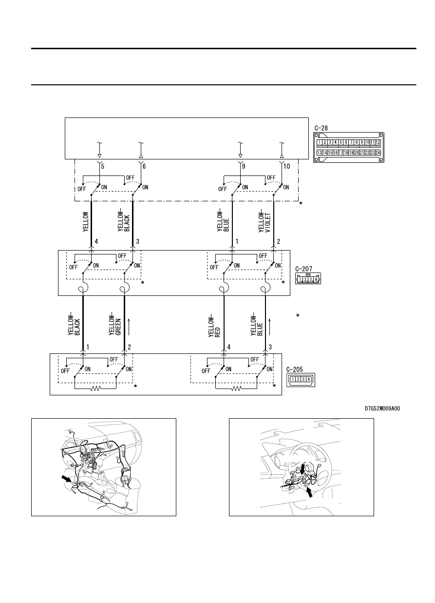
DTC B1B06: Driver's Air Bag Module (2nd squib) System (Squib Circuit Open)

M15204000929USA0000010000

SRS-ECU

DRIVER'S AIR BAG 
MODULE (SQUIB)

CLOCK 
SPRING

Driver's Air Bag Modle (Squib) Circuit

: CONNECTOR LOCK SWITCH
  CONNECTOR COUPLED : ON
  CONNECTOR UNCOUPLED : OFF

NOTE

ZC6008760000

Connector: C-28

C-28 (Y)

ZC6008770004

Connectors: C-205, C-207

C-205 (Y)

C-207 (Y)

SUPPLEMENTAL RESTRAINT SYSTEM (SRS)

52B-59

SRS AIR BAG DIAGNOSIS


If DTCB1B02 <1st squib> or B1B06 <2nd squib> is
set  in  the  SRS-ECU,  always  diagnose  the  CAN
main bus line.

CIRCUIT OPERATION

The SRS-ECU judges how severe a collision is by
detecting signals from the front impact sensors and
the front air bag analog G-sensor. If the impact is
over a predetermined level, the SRS-ECU sends an
ignition signal. At this time, if the front air bag safing
G-sensor is on, the SRS air bag will inflate.

The ignition signal is input to the air bag module via
the clock spring to inflate the air bag.

DTC SET CONDITIONS

This  DTC  is  set  if  there  is  abnormal  resistance
between the input terminals of the driver's air bag

module (squib). The most likely causes for this code
to be set are the followings:

Open  circuit  in  the  driver's  air  bag  module
(squib) or harness

Open circuit in the clock spring

Malfunction of connector contact

TROUBLESHOOTING HINTS

Open circuit in the clock spring

Open circuit due to improper neutral position of the
clock spring

Open circuit in the driver's air bag module (squib)
circuit

Disengaged  driver's  air  bag  module  (squib)
connector

Improper connector contact

Malfunction of the SRS-ECU

DIAGNOSIS

Required Special Tools:

MB991958: Scan Tool (M.U.T.-III Sub Assembly)

MB991824: Vehicle Communication Interface (V.C.I.)

MB991827: M.U.T.-III USB Cable

MB991910:  M.U.T.-III  Main  Harness  A  (Vehicles  with
CAN Communication System)

MB991865: Dummy resistor

MB991866: Resister harness

52B-60

SUPPLEMENTAL RESTRAINT SYSTEM (SRS)

SRS AIR BAG DIAGNOSIS

STEP 1. Using scan tool MB991958, diagnose the CAN bus
line.

ZC501967

AC404789

ZC5019680000

MB991824

MB991827

MB991910

Data link

connector

To prevent damage to scan tool MB991958, always turn the
ignition  switch  to  the  "LOCK"  (OFF)  position  before
connecting or disconnecting scan tool MB991958.

(1)

Connect scan tool MB991958. Refer to "How to connect the
scan tool P.52B-31."

(2)

Turn the ignition switch to the "ON" position.

(3)

Diagnose the CAN bus line.

(4)

Turn the ignition switch to the "LOCK" (OFF) position.

Q:Is the CAN bus line found to be normal?

YES:

 Go to Step 2.

NO:

 Repair the CAN bus line (Refer to GROUP 54D,

Diagnosis P.54D-17).

STEP 2. Recheck for diagnostic trouble code.

ZC501967

AC404789

ZC5019680000

MB991824

MB991827

MB991910

Data link

connector

Check again if the DTC is set.

(1)

Erase the DTC.

(2)

Turn the ignition switch to the "ON" position.

(3)

Check if the DTC is set.

(4)

Turn the ignition switch to the "LOCK" (OFF) position.

Q:Is the DTC set?

YES:

 Go to Step 3.

NO:

 There is an intermittent malfunction such as poor

engaged connector(s) or open circuit (Refer to GROUP 00,
How to Cope with Intermittent Malfunction P.00-15).

STEP 3. Check the driver's air bag module. (Using scan tool
MB991958, read the diagnostic trouble code.)

(1)

Disconnect the negative battery terminal.

(2)

Slide  the  outer  housing  of  the  driver’  s  air  bag  module
connector  C-205  in  the  arrow  direction  shown,  and
disconnect the connector.

SUPPLEMENTAL RESTRAINT SYSTEM (SRS)

52B-61

SRS AIR BAG DIAGNOSIS

ZC600213

Outer housing of the driver's air bag  
module connector 

0001

ZC600207

C-205 Air bag  
module connector

MB991866 (Resistor 
 harness)

MB991865 (Dummy  
resistor : 3 


)

0000

(3)

Connect special tool MB991865 to special tool MB991866.

Do not insert a test probe into the terminal from its front side
directly,  as  the  connector  contact  pressure  may  be
weakened.

(4)

Insert special tool MB991866 into clock spring side of driver’s
air bag module connector C-205 (terminal No.1 and 2 <1st
squib> or terminal No.3 and 4 <2nd squib>) by backprobing.

(5)

Connect the negative battery terminal.

Always DTC B1B06 is set when checking DTC B1B02. This
is  because  the  second  side  terminal  is  isolated  when
checking  it.  DTC  B1B06  is  set  but  this  is  not  a  fault.  In
addition,  always  DTC  B1B02  is  set  when  checking  DTC
B1B06 because the first side terminal is isolated.

(6)

Erase the diagnostic trouble code memory, and check the
diagnostic trouble code.

Q:Is the checked DTC set?

YES:

 Go to Step 4.

NO:

 Replace the driver's air bag module. (Refer to P.

52B-329). Then go to Step 6.

STEP 4. Check the clock spring. (Using scan tool MB991958,
read the diagnostic trouble code.)

(1)

Disconnect the negative battery terminal.

(2)

Disconnect the clock spring connector C-207.

ZC600208

C-207 Harnnes side 
connector

MB991866 (Resistor 
 harness)

MB991865 (Dummy  
resistor : 3 


)

0000

(3)

Connect special tool MB991865 to special tool MB991866.

Do not insert a probe into the terminal from its front side
directly,  as  the  connector  contact  pressure  may  be
weakened.

(4)

Insert  special  tool  MB991866  into  harness  side  of  clock
spring connector C-207 (terminal No.3 and 4 <1st squib> or
terminal No.1 and 2 <2nd squib>) by backprobing.

(5)

Connect the negative battery terminal.

Always DTC B1B06 is set when checking DTC B1B02. This
is  because  the  second  side  terminal  is  isolated  when
checking  it.  DTC  B1B06  is  set  but  this  is  not  a  fault.  In
addition,  always  DTC  B1B02  is  set  when  checking  DTC
B1B06 because the first side terminal is isolated.

(6)

Erase the diagnostic trouble code memory, and check the
diagnostic trouble code.

Q:Is the checked DTC set?

YES:

 Go to Step 5.

NO:

 Replace the clock spring. (Refer to P.52B-329). Then

go to Step 6.

STEP 5. Check the harness between the SRS-ECU
connector C-28 (terminal No.5 and 6 <1st squib> or terminal

52B-62

SUPPLEMENTAL RESTRAINT SYSTEM (SRS)

SRS AIR BAG DIAGNOSIS


Content   ..  880  881  882  883   ..