Mitsubishi Outlander XL. Manual - part 774


  Index      Mitsubishi     Mitsubishi Outlander XL - service repair manual 2007 year


Search            copyright infringement  


Content   ..  772  773  774  775   ..


Mitsubishi Outlander XL. Manual - part 774


Q:Is the DTC set?

YES:

 Replace KOS-ECU and register the ID codes. (Refer

to P.42B-12.) After registering the ID codes, go to Step
3.

NO:

 The procedure is complete.

STEP 3. Recheck for diagnostic trouble code.
Check again if the DTC is set to the KOS-ECU.

(1)

Turn the ignition switch to the "ON" position.

(2)

Check if the DTC is set.

Q:Is the DTC set?

YES:

 Replace the engine control module and record the

VIN. (Refer to GROUP 00 - How To Perform Vehicle
Identification Number (VIN) Writing P.00-26.)

NO:

 The procedure is complete.

DTC B2352: Antenna fail

M14209100094USA0000010000

When  replacing  the  ECU,  always  check  that  the
communication circuit is normal.

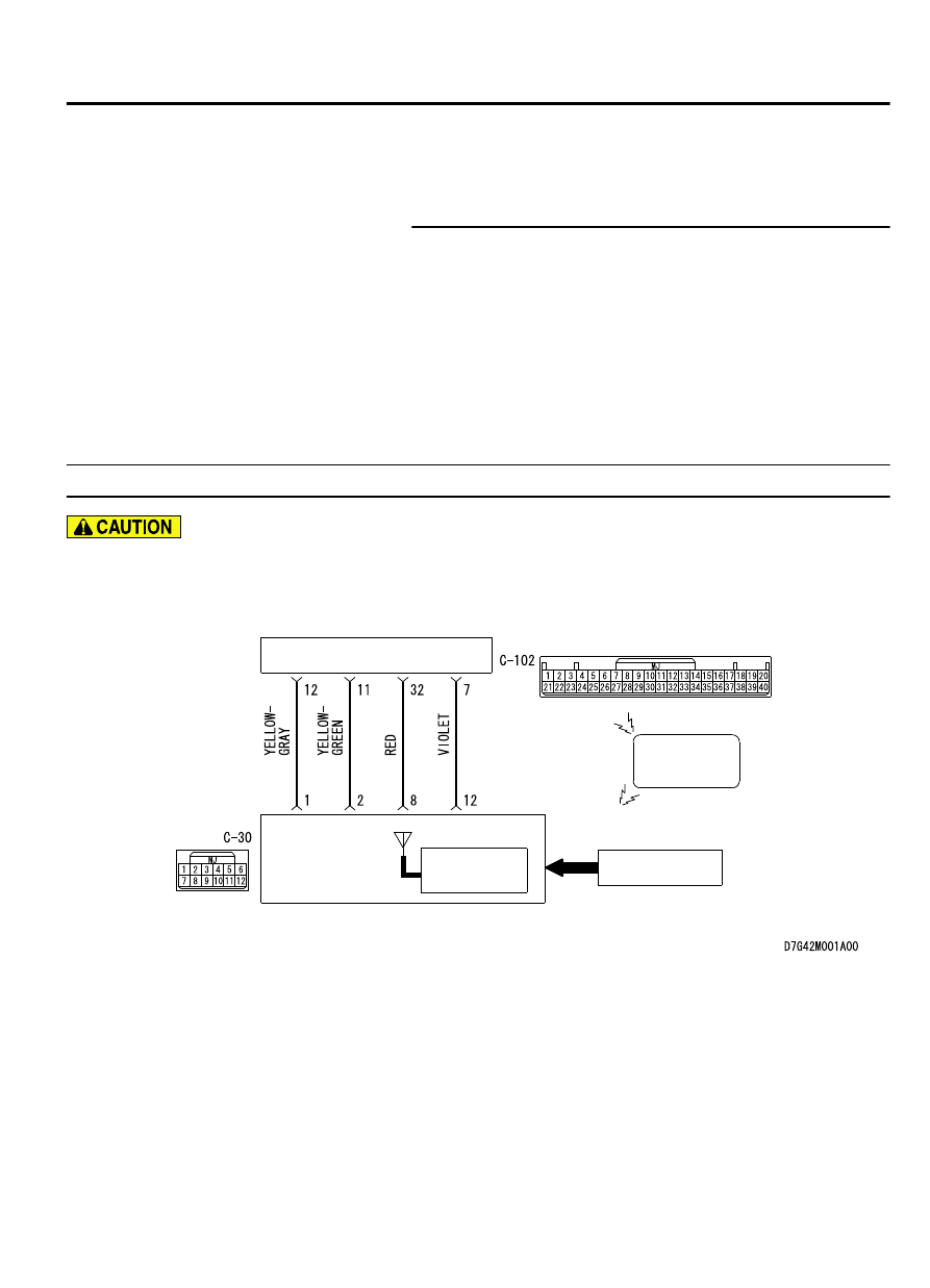
Receiver Antenna  Module and KOS-ECU Circuit

IGNITION
KEY RING
ANTENNA

KEYLESS
OPERATION
KEY

RECEIVER ANTENNA
MODULE

KOS-ECU

ENCRYPTED CODE

TRANSPONDER

KEYLESS OPERATION SYSTEM (KOS)

42B-39

DIAGNOSIS

ZC6008750035

Connector: C-30, C-102

C-30

C-102

DTC SET CONDITION
If  an  open  circuit  or  short  to  ground  occurs  in  the
antenna, KOS-ECU sets the DTC B2352.

TECHNICAL DESCRIPTION (COMMENT)
When  the  ignition  switch  is  turned  ON,  KOS-ECU
sends  signals  to  the  receiver  antenna  module.  The
receiver  antenna  transmits  random  numbers  to  the
emergency key when it receives signals from KOS-

ECU. If an open circuit or short to ground occurs on
the wiring harness between KOS-ECU and receiver
antenna at this time, KOS-ECU determines that there
is a problem.

TROUBLESHOOTING HINTS

Malfunction of the receiver antenna module

Damaged wiring harness and connectors

Malfunction of KOS-ECU

DIAGNOSIS

Required Special Tools:

MB991958: Scan Tool (M.U.T.-III Sub Assembly)

MB991824: Vehicles Communication Interface (V.C.I.)

MB991827: M.U.T.-III USB Cable

MB991910:  M.U.T.-III  Main  Harness  A  (Vehicles  with
CAN communication system)

STEP 1. Using scan tool MB991958, read the diagnostic
trouble code.
Check the DTC B2415 is set to the KOS-ECU.

42B-40

KEYLESS OPERATION SYSTEM (KOS)

DIAGNOSIS

ZC501967

AC404789

ZC5019680000

MB991824

MB991827

MB991910

Data link

connector

To prevent damage to scan tool MB991958, always turn the
ignition  switch  to  the  "LOCK"  (OFF)  position  before
connecting or disconnecting scan tool MB991958.

(1)

Connect scan tool MB991958. Refer to "How to connect scan
too (M.U.T.-III) P.54Af-4."

(2)

Turn the ignition switch to the "ON" position.

(3)

Check if DTC is set.

(4)

Turn the ignition switch to the "LOCK" (OFF) position.

Q:Is the DTC B2415 is set?

YES:

 Refer to P.42B-75.

NO:

 Go to Step 2.

STEP 2. Check receiver antenna module connector C-30
and KOS-ECU connector C-102 for loose, corroded or
damaged terminals, or terminals pushed back in the
connector.

Q:Is the receiver antenna module connector C-30 and KOS-

ECU connector C-102 in good condition?

YES:

 Go to Step 3.

NO:

 Repair the defective connector.

STEP 3. Check the wiring harness between the receiver
antenna module connector C-30 (terminal No. 1, 2) and the
KOS-ECU connector C-102 (terminal No. 11, 12).

Check the signal lines for open circuit and short circuit.

Q:Is the wiring harness between receiver antenna module

connector  C-30  (terminal  No.  1,  2)  and  the  KOS-ECU

connector C-102 (terminal No. 11, 12) in good condition?

YES:

 Go to Step 4.

NO:

 The wiring harness may be damaged or the connector

(s) may have loose, corroded or damaged terminals, or
terminals pushed back in the connector. Repair the wiring
harness as necessary.

STEP 4. Replace the receiver antenna module, and check
whether the diagnostic trouble code is reset.

(1)

Erase the DTC.

(2)

Turn the ignition switch from the "LOCK" (OFF) position to
the "ON" position.

(3)

Check if the DTC is set.

Q:Is the DTC set?

YES:

 Replace KOS-ECU and register the ID codes. (Refer

to P.42B-12.)

KEYLESS OPERATION SYSTEM (KOS)

42B-41

DIAGNOSIS

NO:

 The procedure is complete.

DTC B2400: KOS key registration fail

M14209100014USA0000010000

If the DTC B2400 is set, diagnose the CAN bus
lines.

When replacing the ECU, always check that the
communication circuit is normal.

DTC SET CONDITION
If the registration of the keyless operation key ID to
KOS-ECU fails, KOS-ECU sets the DTC B2400.

TECHNICAL DESCRIPTION (COMMENT)
Assuming  that  another  keyless  operation  key  has
already  been  registered  with  KOS-ECU,  if  the

registration of the keyless operation key ID fails when
a new keyless operation key is added or the existing
key is replaced, KOS-ECU determines that there is a
problem.

TROUBLESHOOTING HINTS

Keyless operation key ID registration failure

Malfunction of the keyless operation key

Malfunction of KOS-ECU

Malfunction of CAN bus line

DIAGNOSIS

Required Special Tools:

MB991958: Scan Tool (M.U.T.-III Sub Assembly)

MB991824: Vehicles Communication Interface (V.C.I.)

MB991827: M.U.T.-III USB Cable

MB991910:  M.U.T.-III  Main  Harness  A  (Vehicles  with
CAN communication system)

STEP 1. Using scan tool MB991958, diagnose the CAN bus
line.

ZC501967

AC404789

ZC5019680000

MB991824

MB991827

MB991910

Data link

connector

To prevent damage to scan tool (MB991958), always turn
the  ignition  switch  to  the  "LOCK"  (OFF)  position  before
connecting or disconnecting scan tool (MB991958).

(1)

Connect scan tool MB991958 to the data link connector.

(2)

Turn the ignition switch to the "ON" position.

(3)

Diagnose the CAN bus line.

(4)

Turn the ignition switch to the "LOCK" (OFF) position.

Q:Is the CAN bus line found to be normal?

YES:

 Go to Step 2.

NO:

 Repair the CAN bus line. (Refer to GROUP 54D,

Diagnosis P.54D-17).

42B-42

KEYLESS OPERATION SYSTEM (KOS)

DIAGNOSIS


Content   ..  772  773  774  775   ..