Mitsubishi Outlander XL. Manual - part 752
ZC600113
2
1
3
0000
4
4
20 ± 5 N·m
15 ± 3 ft-lb
4.0 ± 2.0 N·m
35 ± 17 in-lb
2.5 ± 0.5 N·m
23 ± 4 in-lb
9.0 ± 1.0 N·m
79 ± 9 in-lb
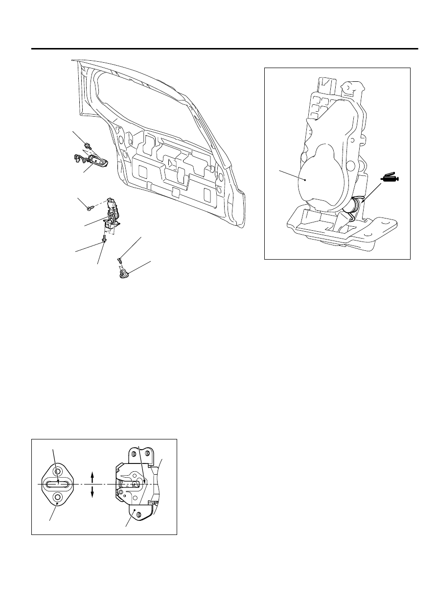
Striker removal steps
·
Liftgate trim (Refer to GROUP 52A,
Liftgate Trim P.52A-14.)
>>A<<
1.
Striker
Liftgate lock release handle removal
steps
·
Liftgate trim (Refer to GROUP 52A,
Liftgate Trim P.52A-14.)
·
Rear wiper motor assembly (Refer to
GROUP 51B, Rear Wiper and
Washer P.51B-57.)
Liftgate lock release handle removal
steps
2.
Liftgate lock release handle
Liftgate latch removal steps
·
Liftgate trim (Refer to GROUP 52A,
Liftgate Trim P.52A-14.)
3.
Ground bolt
4.
Liftgate latch assembly
INSTALLATION SERVICE POINT
>>A<< STRIKER INSTALLATION
ZC6001140000
+1.5 mm
(0.06 in)
-1.5 mm
(0.06 in)
Striker center
Striker
Latch center
Latch
Install the striker so that the striker center does not deviate more
than ±1.5 mm (0.06 inch) from the latch center.
LIFTGATE
42Ac-11
LIFTGATE HANDLE AND LATCH