Mitsubishi Outlander XL. Manual - part 708
 

  Index      Mitsubishi     Mitsubishi Outlander XL - service repair manual 2007 year


Search            


Content   ..  706  707  708  709   ..


Mitsubishi Outlander XL. Manual - part 708


ZC5018330000

5

1

9

9

6

7

11

7

2

3

4

1

11

8

10

N

Claw

Claw

Claw

Claw

<Vehicles without remote 
controlled audio switch>

<Vehicles with remote 
controlled audio switch>

2.5 ± 0.5 N·m 
22.1 ± 4.4 in-lb

9.5 ± 2.5 N·m 
84 ± 22 in-lb

9.5 ± 2.5 N·m 
84 ± 22 in-lb

44 ± 11 N·m 
33 ± 8 ft-lb

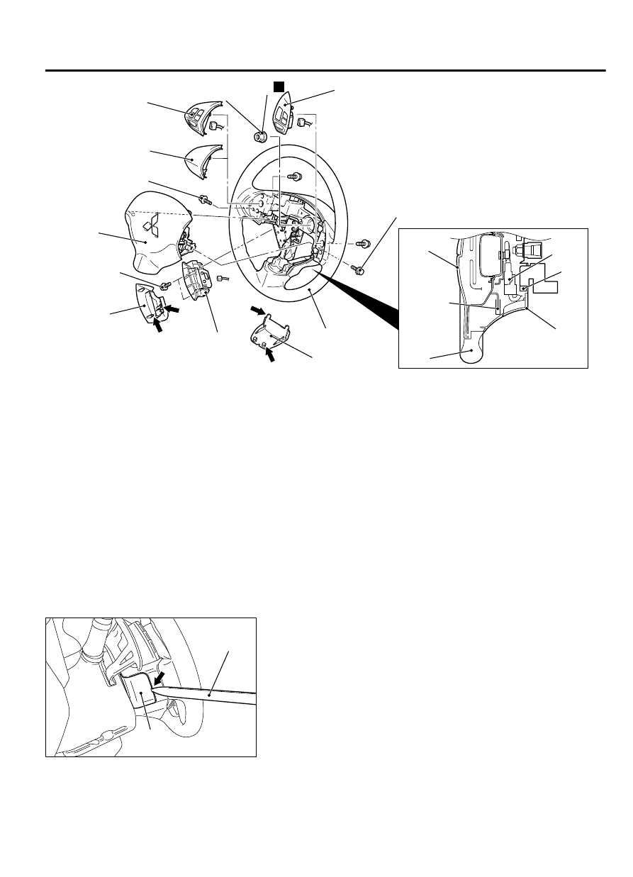
Removal steps

<<A>>

1.

Cover

>>B<<

2.

Horn connector connection

>>B<<

3.

Audio  control  switch  connector
connection  <Vehicles  with  audio
control switch>

<<B>>

>>B<<

4.

Air bag module connector connection

5.

Telematic cover

6.

Telematic switch

Removal steps

<<C>>

7.

Air bag module

8.

Cruise control switch

9.

Bezel  switch  or  Remote  controlled
radio switch

10. Self-locking nut

<<D>>

>>A<<

11. Steering wheel assembly

Required Special Tools:

⦆

MB990784: Ornament Remover

⦆

MB990803: Steering wheel puller

REMOVAL SERVICE POINTS

<<A>> COVER REMOVAL

ZC501834

Cover

0000

MB990784

Insert  the  special  tool  MB990784  at  the  indicated  position  to
remove the cover.

NOTE: 

The special tool MB990784 can be inserted through the

notch behind the area shown.


POWER STEERING

37-21

STEERING WHEEL

<<B>> AIR BAG MODULE ASSEMBLY CONECTOR
DISCONNECTION

ZC601709

AC600868

Outer housing of the driver’s air bag  
module connector

Horn connector

Lower column cover

0000

Driver’s air bag  
module connector
(4-pin, yellow)

Slide the outer housing of the driver's air bag module connector
in the arrow direction shown, and disconnect the connector.


<<C>> AIR BAG MODULE REMOVAL

⦆

Never  use  an  electric  tester  to  diagnose  the  air  bag
module circuit. Never attempt to disassemble the air bag
module.

⦆

Be sure to store the removed air bag module in a clean
and dry place with a pad surface facing upward.


<<D>> STEERING WHEEL ASSEMBLY REMOVAL

1.

Position the steering wheel in a straight ahead direction.

Use the special tool to remove the steering wheel since the
steering  column  collision  absorbing  mechanism  may  be
damaged.

37-22

POWER STEERING

STEERING WHEEL

ZC501836

MB990784

0000

2.

Use special tool MB990803 to remove the steering wheel

INSTALLATION SERVICE POINTS

>>A<< STEERING WHEEL ASSEMBLY INSTALLATION
After centering the clock spring (Refer to GROUP 52B - Air Bag
Module  Clock  Spring  P.52B-329.),  install  the  steering  wheel
assembly.

>>B<< AIR BAG MODULE CONNECTOR CONNECTION/
AUDIO CONTROL SWITCH CONNECTOR CONNECTION/
HORN CONNECTOR CONNECTION
Connect the connector securely and route the harnesses not to
lie off the cover hole.

STEERING SHAFT

REMOVAL AND INSTALLATION

M13702000115USA0000010000

⦆

Before  removing  the  steering  wheel/air  bag
module assembly, refer to GROUP 52B - Service
Precautions  P.52B-28and 
 Air  Bag  Module
Clock Spring P.52B-329.

⦆

After the installation, perform a calibration for
the ASC-ECU to learn the steering wheel sensor
neutral point. (Refer to GROUP 35C, On-vehicle
Service - Steering Wheel Sensor Calibration P.
35C-192.)

Pre-removal operation

⦆

Air  Bag  Module  and  Steering  Wheel  Assembly
Removal (Refer to P.37-20.)

⦆

Bottom Cover Assembly (Driver’s seat) and Side
Lower  Panel  Assembly  Removal  (Refer  to
GROUP  52A  -  Instrument  Panel  Assembly
Removal and Installation P.52A-2.)

⦆

Lower side cover (L) Removal (Refer to GROUP
52A  -  Front  Floor  Console  Assembly  Removal
and Installation P.52A-8.)

⦆

WCM  vehicles  with  WCM/Receiver  Antenna
Module  vehicles  with  KOS  Removal  (Refer  to
GROUP  54Ag,  Ignition  Switch  -  On-vehicle
Service  -  Ignition  Switch  Removal  and
Installation P.54Ag-13.)

Post-installation operation

⦆

WCM  vehicles  with  WCM/Receiver  Antenna
Module vehicles with KOS Installation (Refer to
GROUP  54Ag,  Ignition  Switch  -  On-vehicle
Service  -  Ignition  Switch  Removal  and
Installation P.54Ag-13.)

⦆

Lower  side  cover  (L)  Installation  (Refer  to
GROUP  52A  -  Front  Floor  Console  Assembly
Removal and Installation P.52A-8.)

⦆

Bottom Cover Assembly (Driver’s seat) and Side
Lower  Panel  Assembly  Installation  (Refer  to
GROUP  52A  -  Instrument  Panel  Assembly
Removal and Installation P.52A-2.)

⦆

Air  Bag  Module  and  Steering  Wheel  Assembly
Installation (Refer to P.37-20.)

POWER STEERING

37-23

STEERING SHAFT

⦆

Confirm that the steering wheel is at the straight-
ahead position.

⦆

Steering  wheel  sensor  calibration  (Refer  to
GROUP  35C,  On-vehicle  Service  -  Steering
Wheel Sensor Calibration P.35C-192.)

ZC5018370000

A

A

5

9

3

2

6

7

1

8

4

10

Section A-A

Claw

Column 
Cover

2.5 ± 0.5 N·m 
22.1 ± 4.4 in-lb

2.5 ± 0.5 N·m 
22.1 ± 4.4 in-lb

2.5 ± 0.5 N·m 
22.1 ± 4.4 in-lb

7.0 ± 3.0 N·m 
61 ± 26 in-lb

12 ± 3 N·m 
102 ± 26 in-lb

20 ± 5 N·m 
15 ± 3 ft-lb

28 ± 7 N·m 
21 ± 5 ft-lb

Removal steps

<<A>>

1.

Knob cap <Vehicles with KOS>

2.

Ignition key cover

3.

Steering column lower cover

4.

Steering column protector

5.

Steering column upper cover

6.

Paddle  shift  assembly  vehicles  with
paddle shift

>>B<<

7.

Steering  wheel  sensor/clock  spring
column  switch  assembly  (Refer  to
GROUP  35C  -  Steering  Angle
Sensor P.35C-198and GROUP 52B -
Driver  side·passenger  side  air  bag
module clock spring P.52B-329.)

Removal steps

8.

Key interlock cable (Refer to GROUP
23A - A/T Key Interlock And Shiftlock
Mechanisms P.23A-168.)

<<B>>

9.

Steering shaft cover

<<C>>

>>A<<

10. Steering column shaft assembly

37-24

POWER STEERING

STEERING SHAFT


Content   ..  706  707  708  709   ..