Mitsubishi Outlander XL. Manual - part 706
TOOL
TOOL NUMBER
AND NAME
SUPERSESSION APPLICATION
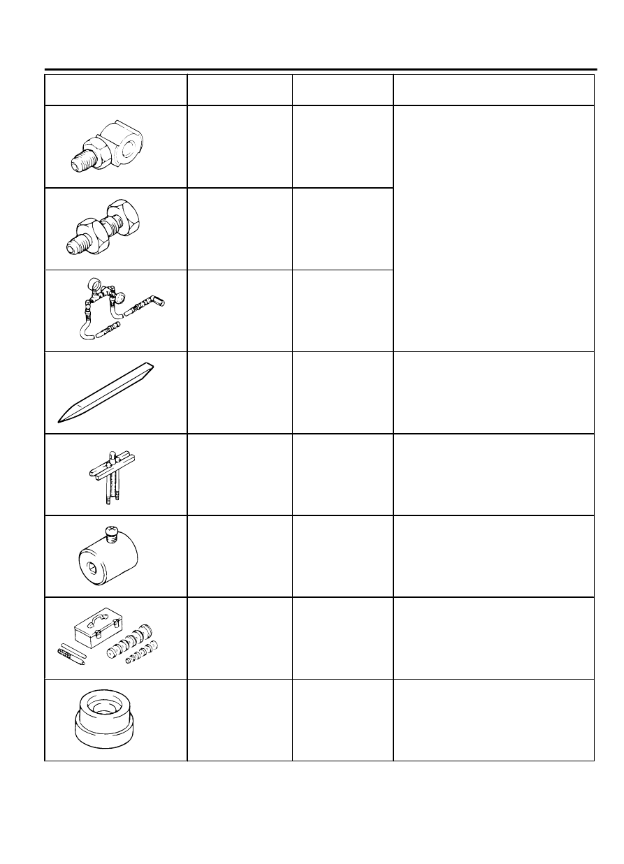
MB991548
MB991548
Power steering oil
pressure gauge
adapter (Pump
side)
MB991548-01
Oil pump pressure test
MB991549
MB991549
Power steering oil
pressure gauge
adapter (Hose
side)
MB991549-01
MB990662
MB990662
Power steering oil
pressure gauge
MB990662-01
MB990784
MB990784
Ornament remover
General service
tool
Cover removal
MB990803
MB990803
Steering wheel
puller
-
Steering wheel removal
MB991006
MB990228 or
MB991006
Preload socket
MB990228-01
Steering gear total pinion torque check
MB990925
MB990925
Bearing and oil seal
installer set
MB990925-01 or
general service
tool
⦆
Oil seal and bearing installation
⦆
MB990927, MB990938, MB990939.
MB991203
MB991203
Oil seal and
bearing installer
Tool not available Oil seal and bearing installation
POWER STEERING
37-13
SPECIAL TOOLS