Mitsubishi Outlander XL. Manual - part 707
ZC501797
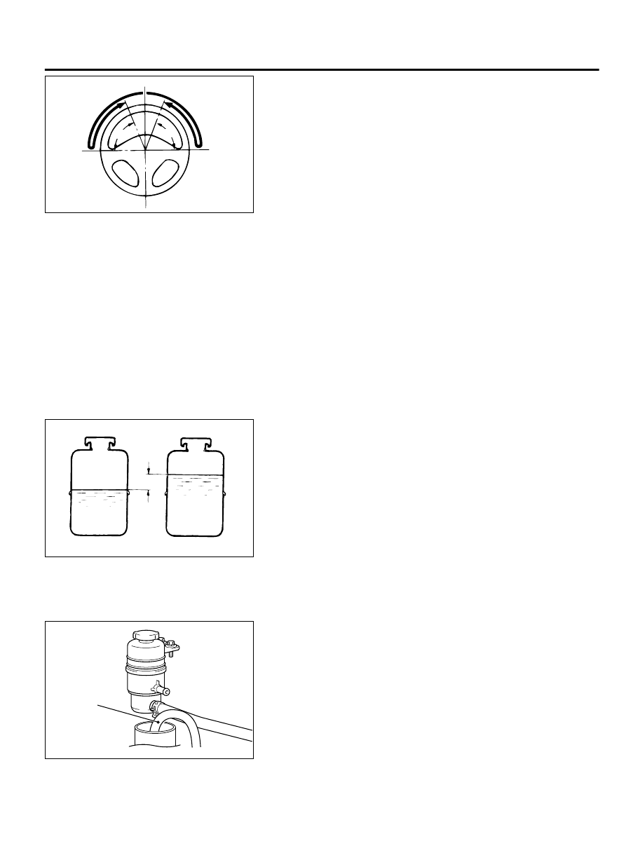
70°
70°
0000
2.
At a vehicle speed of approximately 35 km/h (22 mph), turn
the steering wheel 90 degrees, hold a few seconds, then
release. If the steering wheel then returns 70 degrees or more,
the return can be judged satisfactory.
NOTE:
There will be a momentary feeling or "heaviness"
when the wheel is turned quickly, but this is not
abnormal. (Oil pump discharge amount is especially apt to
be insufficient during idling.)
DRIVE BELT TENSION CHECK
M13702000019USA0000010000
Refer to GROUP 11A Drive belt tension check adjustment P.
11A-9.
FLUID LEVEL CHECK
M13702000020USA0000010000
1.
Park the vehicle on a flat, level surface.
2.
Start the engine, and then turn the steering wheel several
times to raise the temperature of the fluid to approximately 50
- 60°C (122 - 140°F).
3.
With the engine running, turn the wheel all the way to the left
and right several times.
ZC5017980000
With engine running
With engine stopped
Fluid level change: Within 5 mm (0.2 in)
4.
Check the fluid in the oil reservoir for foaming or milkiness.
Check the difference of the fluid level when the engine is
stopped, and while it is running. If the change of the fluid level
is 5 mm (0.2 inch) or more, air bleeding should be done.
FLUID REPLACEMENT
M13702000021USA0000010000
1.
Raise and support the front wheels.
ZC5017990000
RETURN HOSE
2.
Disconnect the return hose connection, and then connect a
vinyl hose to the return hose, and drain the fluid into a
container.
3.
Disconnect the ignition coil connectors. (Refer to GROUP 16c,
Ignition coil removal and installation P.16c-6).
4.
While operating the starter motor intermittently, turn the
steering wheel all the way to the left and right several times to
drain all of the fluid.
5.
Connect the return hose securely, and then secure with the
clip.
POWER STEERING
37-17
ON-VEHICLE SERVICE