Mitsubishi Outlander XL. Manual - part 709


  Index      Mitsubishi     Mitsubishi Outlander XL - service repair manual 2007 year


Search            


Content   ..  707  708  709  710   ..


Mitsubishi Outlander XL. Manual - part 709


REMOVAL SERVICE POINTS

<<A>> KNOB CAP REMOVAL
Remove the knob cap while pressing the two projections.

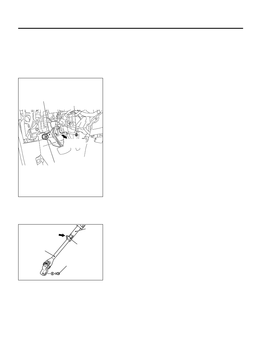
<<B>> STEERING SHAFT COVER REMOVAL

ZC501838

Steering shaft cover

Tear off
floor carpet

Clip
(Lock floor carpet)

Clip
(Lock cover steering shaft)

0000

1.

Remove the clip (for securing the floor carpet), and turn back
the floor carpet.

2.

Remove the clip (for securing the steering shaft cover), and
then remove the steering shaft cover.


<<C>> STEERING COLUMN SHAFT ASSEMBLY
DISCONNECTION

AC511457
AC511459

ZC5018390000

Shaft A

Shaft B

Clip

Claw

Steering 
column bolt

1.

Remove the steering column bolt connecting the steering gear
to the steering column assembly.

2.

Disconnect  the  steering  gear  from  the  steering  column
assembly while sliding the shaft A to the shaft B with the clip
claw as shown in the figure is pinched.

3.

Remove the steering column mounting bolt.

POWER STEERING

37-25

STEERING SHAFT

INSTALLATION SERVICE POINTS

>>A<< STEERING COLUMN SHAFT ASSEMBLY
INSTALLATION


Ensure that the tilt lever is in the lock position, and install the
steering column as below.

ZC501840

Bolt hole 
(No tapped hole)

Bolt hole 
(Tapped hole)

Yoke steering column
assembly

2

1

3

4

Tilt
lever

0000

4

1.

Hand-tighten the mounting bolts in the order of 1, 2, 3, and
tighten them in the order of 3, 2, 1 to the specified torque.

Tightening torque:
Mounting bolt 1: 28 ± 7 N·m (21 ± 5 ft-lb)
Mounting bolt 2, 3: 12 ± 3 N·m (102 ± 26 in-lb)

2.

Assemble the steering column assembly to the steering gear.

3.

Insert the bolt connecting the steering column assembly with
the steering gear into the non-threaded bolt hole.

4.

Tighten the mounting bolt 4 to the specified torque.

Tightening torque: 20 ± 5 N·m (15 ± 3 ft-lb)


>>B<< STEERING WHEEL SENSOR CLOCK SPRING
COLUMN SWITCH ASSEMBLY INSTALLATION

ZC501841

Mating marks

0000

If the center of the clock spring is not correctly aligned, the
steering wheel may not be turned fully or the cable inside
the clock spring may be broken, causing the SRS air bag to
be inoperative or operated incorrectly.

1.

Align the mating marks of the clock spring.
Alignment of mating marks

(1)

Turn the clock spring clockwise fully.

(2)

Turn  the  clock  spring  counterclockwise  approximately
three and 3/4 turns to align the mating marks.

(3)

Install the clock spring to the column switch.

37-26

POWER STEERING

STEERING SHAFT

ZC5018420000

Steering wheel sensor

Mating mark

Be sure to align the steering wheel sensor neutral position
mark.  If  the  neutral  position  marks  are  not  aligned,  the
steering wheel operation may damage the steering wheel
sensor.

2.

Align the steering wheel sensor neutral position mark.
Alignment of mating marks

(1)

When checking the neutral position check window of the
steering wheel sensor, if an arrow can be seen, turn to the
direction of the arrow, and align the neutral position mark
as shown in the figure.

(2)

Install  the  steering  wheel  sensor  to  the  column  switch
assembly, correctly maintaining the neutral position.

(3)

Install the column switch assembly to the vehicle, correctly
maintaining the neutral position.

DISASSEMBLY AND ASSEMBLY

M13702000117USA0000010000

ZC5018430000

2

1

3

Disassembly steps

<<A>>

>>A<<

1.

Steering locking bolt

>>A<<

2.

Steering lock assembly

Disassembly steps

3.

Steering column shaft assembly

POWER STEERING

37-27

STEERING SHAFT

DISASSEMBLY SERVICE POINT

<<A>> STEERING LOCK BOLT REMOVAL

ZC5018440000

Steering lock 
assembly

Steering lock 
assembly

Reverse screw tap

Steering  
lock bolt

1.

Use a drill to make a hole just deeply enough for the tap to
stand on the steering lock bolt.

2.

Use a left-hand thread tap to remove the steering lock bolt.

ASSEMBLY SERVICE POINT

>>A<< STEERING LOCK ASSEMBLY/STEERING LOCKING
BOLT INSTALLATION

1.

When  installing  the  steering  lock  assembly  to  the  steering
column  shaft  assembly,  temporarily  assemble  the  steering
lock assembly while aligning it with the boss on the column.

ZC5018450000

2.

Make sure that the steering lock operates normally, and then
tighten the steering lock bolt until its head is broken off.

POWER STEERING GEAR BOX AND LINKAGE

REMOVAL AND INSTALLATION

M13702000109USA0000010000

Before removing the steering wheel and airbag
module,  refer  to  GROUP  52B  -  Service
Precautions  and  Airbag  Module  and  Clock
Spring.  Position  the  front  wheels  in  a  straight
ahead direction. If you fail to do this, the clock
spring  for  SRS  may  be  damaged,  making  the
SRS  (air  bag)  inoperable  which  may  cause
serious injury to the driver.

*The bolts and nuts marked with*are coated with
the friction coefficient stabilizer. When removed
these  parts,  make  sure  that  they  are  free  of
damage,  remove  any  dust  and  dirt  on  the
bearing surfaces and the threads, and tighten to
the specified torque.

37-28

POWER STEERING

POWER STEERING GEAR BOX AND LINKAGE


Content   ..  707  708  709  710   ..