Mitsubishi Outlander XL. Manual - part 321
ZK603379
2
1
16 15 14 13 12 11 10 9 8 7 6 5 4 3
2
1
32 31 30 29 28 27 26 25 24 23 22 21 20 19 18 17
48 47 46 45 44 43 42 41 40 39 38 37 36 35 34 33
64 63 62 61 60 59 58 57 56 55 54 53 52 51 50 49
AA00
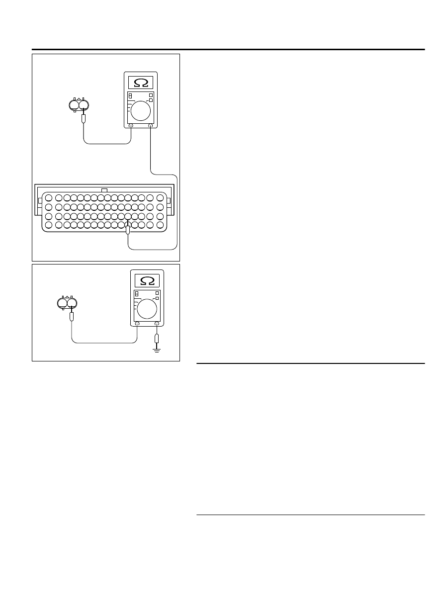
B-07 Harness
connector:
component side
B-10 Harness
connector:
component side
(2)
Measure the evaporative emission purge solenoid connector
B-07 (terminal No. 1) and the ECM connector B-10 (terminal
No. 37).
⦆
Should be less than 2 ohms.
2
1
ZK604094
B-07 Harness
connector:
component side
AA00
(3)
Check for the evaporative emission purge solenoid
connector B-07 (terminal No. 1) and ground.
⦆
Not continuity.
Q:Is the harness wire in good condition?
YES:
Go to Step 6.
NO:
Repair it. Then go to Step 7.
STEP 6. Check the trouble symptoms.
(1)
Carry out a test drive with the drive cycle pattern. Refer to
Diagnostic Function - OBD-II Drive Cycle - Pattern 24 P.
13Ab-8.
(2)
Check the diagnostic trouble code (DTC).
Q:Is DTC P0443 set?
YES:
Replace the ECM. When the ECM is replaced, register
the ID code. Refer to GROUP 42B, ID Code Registration
Judgment Table <Vehicles with KOS> P.42B-12or GROUP
42C, ID Code Registration Judgment Table <Vehicles with
WCM> P.42C-8. Then go to Step 7.
NO:
It can be assumed that this malfunction is
intermittent. Refer to GROUP 00, How to Use
Troubleshooting/Inspection Service Points - How to Cope
with Intermittent Malfunctions P.00-15.
STEP 7. Test the OBD-II drive cycle.
(1)
Carry out a test drive with the drive cycle pattern. Refer to
Diagnostic Function - OBD-II Drive Cycle - Pattern 24 P.
13Ab-8.
MULTIPORT INJECTION SYSTEM (MFI) <DIAGNOSIS>
13Ab-479
DIAGNOSTIC TROUBLE CODE PROCEDURES