Mitsubishi Outlander XL. Manual - part 322


  Index      Mitsubishi     Mitsubishi Outlander XL - service repair manual 2007 year


Search            


Content   ..  320  321  322  323   ..


Mitsubishi Outlander XL. Manual - part 322


DTC SET CONDITIONS <Circuit continuity - During cranking>
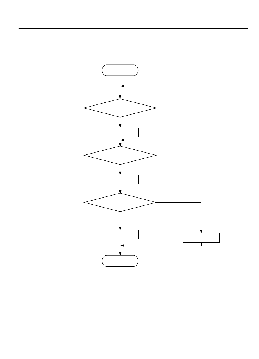
Logic Flow Chart

End

Solenoid “ON”

Yes

No

No

Yes

Was surge voltage 

(>VB+2V) detected?

Monitoring

conditions

Good

Start

ZK604093 AA00

Solenoid “OFF”

Malfunction

Yes

No

200msec have passed?

Check Conditions

Engine is being cranked.

Battery  positive  voltage  is  between  10  and  16.5
volts.

Judgement Criteria

The evaporative emission ventilation solenoid coil
surge voltage (battery positive voltage + 2 volts) is
not detected for 0.2 second.

The ECM monitors for this condition once during the
drive cycle.

MULTIPORT INJECTION SYSTEM (MFI) <DIAGNOSIS>

13Ab-483

DIAGNOSTIC TROUBLE CODE PROCEDURES

DTC SET CONDITIONS <Circuit continuity - During normal operation>

Logic Flow Chart

Good

Malfunction

Solenoid “OFF”

1sec have passed?

Solenoid “ON”

Start

Was surge voltage

(> VB + 2V) detected?

End

No

No

No

No

Yes

Yes

Yes

Yes

Yes

No

ZK603769AA00

Monitoring

conditions

Check Conditions

Battery  positive  voltage  is  between  10  and  16.5
volts.

ON  duty  cycle  of  the  evaporative  emission  purge
solenoid is 0 percent.

Evaporative emission ventilation solenoid is ON.

More  than  1  second  has  elapsed  after  the  above
mentioned conditions have been met.

Judgement Criterion

The evaporative emission ventilation solenoid coil
surge voltage (battery positive voltage + 2 volts) is

not  detected  for  1  second  after  the  evaporative
emission ventilation solenoid is turned OFF.

OBD-II DRIVE CYCLE PATTERN
Refer to Diagnostic Function - OBD-II Drive Cycle -
Pattern 24 P.13Ab-8.

TROUBLESHOOTING HINTS (The most likely
causes for this code to be set are:)

Evaporative emission ventilation solenoid failed.

Harness damage

Connector damage

13Ab-484

MULTIPORT INJECTION SYSTEM (MFI) <DIAGNOSIS>

DIAGNOSTIC TROUBLE CODE PROCEDURES

ECM failed.


DIAGNOSIS

Required Special Tools:

MB991958: Scan Tool (M.U.T.-III Sub Assembly)

MB991824: V.C.I.

MB991827: USB Cable

MB991910: Main Harness A

STEP 1. Using scan tool MB991958, check actuator test item
15: Evaporative Emission Ventilation Solenoid.

ZC501967

AC404789

ZC5019680000

MB991824

MB991827

MB991910

Data link

connector

To prevent damage to scan tool MB991958, always turn the
ignition  switch  to  the  "LOCK"  (OFF)  position  before
connecting or disconnecting scan tool MB991958.

(1)

Connect scan tool MB991958 to the data link connector.

(2)

Turn the ignition switch to the "ON" position.

(3)

Set scan tool MB991958 to the actuator test mode for item
15, Evaporative emission ventilation solenoid.

An operation sound should be heard and vibration should
be felt when the evaporative emission ventilation solenoid
is operated.

(4)

Turn the ignition switch to the "LOCK" (OFF) position.

Q:Is the solenoid operating properly?

YES:

 It can be assumed that this malfunction is

intermittent. Refer to GROUP 00, How to Use
Troubleshooting/Inspection Service Points - How to Cope
with Intermittent Malfunctions P.00-15.

NO:

 Go to Step 2.

STEP 2. Check harness connector A-33X at the MFI relay
connector and harness connector B-11 at the ECM for
damage.

Q:Is the harness connector in good condition?

YES:

 Go to Step 3.

NO:

 Repair it. Refer to GROUP 00E, Harness Connector

Inspection P.00E-2. Then go to Step 7.

STEP 3. Check the evaporative emission ventilation
solenoid.

(1)

Disconnect  the  evaporative  emission  ventilation  solenoid
connector D-116.

MULTIPORT INJECTION SYSTEM (MFI) <DIAGNOSIS>

13Ab-485

DIAGNOSTIC TROUBLE CODE PROCEDURES

AA00

ZK603380

1

2

Evaporative emission
ventilation solenoid
connector

(2)

Measure  the  resistance  between  evaporative  emission
ventilation solenoid side connector terminal No. 1 and No. 2.

Standard value: 17 - 21 Ω [at 20°C (68°F)]

Q:Is the measured resistance between 17 and 21 ohms [at

20°C (68°F)]?

YES:

 Go to Step 4.

NO:

 Replace it. Then go to Step 7.

STEP 4. Measure the power supply voltage at the
evaporative emission ventilation solenoid connector D-116.

(1)

Disconnect  the  evaporative  emission  ventilation  solenoid
connector D-116 and measure at the harness side.

(2)

Turn the ignition switch to the "ON" position.

(3)

Measure the voltage between terminal No. 2 and ground.

Voltage should be battery positive voltage.

ZK603381

1

2

AA00

B-07 Harness
connector:
component side

(4)

Turn the ignition switch to the "LOCK" (OFF) position.

Q:Is the measured voltage battery positive voltage?

YES:

 Go to Step 5.

NO:

 Repair it. Then go to Step 7.

STEP 5. Check for open cicuit and short circuit to ground
and harness damage between the evaporative emission
ventilation solenoid connector D-116 and the ECM
connector B-11.

(1)

Disconnect  the  evaporative  emission  ventilation  solenoid
connector D-116 and the ECM connector B-11.

13Ab-486

MULTIPORT INJECTION SYSTEM (MFI) <DIAGNOSIS>

DIAGNOSTIC TROUBLE CODE PROCEDURES


Content   ..  320  321  322  323   ..