Mitsubishi Outlander XL. Manual - part 309


  Index      Mitsubishi     Mitsubishi Outlander XL - service repair manual 2007 year


Search            


Content   ..  307  308  309  310   ..


Mitsubishi Outlander XL. Manual - part 309


DIAGNOSIS

Required Special Tools:

MB991958: Scan Tool (M.U.T.-III Sub Assembly)

MB991824: V.C.I.

MB991827: USB Cable

MB991910: Main Harness A

STEP 1. Check harness connector B-20 at the knock sensor
2 and harness connector B-10 at ECM for damage.

Q:Is the harness connector in good condition?

YES:

 Go to Step 2.

NO:

 Repair or replace it. Refer to GROUP 00E, Harness

Connector Inspection P.00E-2. Then go to Step 4.

STEP 2. Check for harness damage between knock sensor
2 connector B-20 and ECM connector B-10.

ZK604049

16

15 14 13 12 11 10 9 8 7 6 5 4

3

2

1

32

31 30 29 28 27 26 25 24 23 22 21 20 19 18

17

48

47 46 45 44 43 42 41 40 39 38 37 36 35 34

33

64

63 62 61 60 59 58 57 56 55 54 53 52 51 50

49

1

2

AA00

B-20 harness connector: 
component side

B-10 harness connector: 
component side

(1)

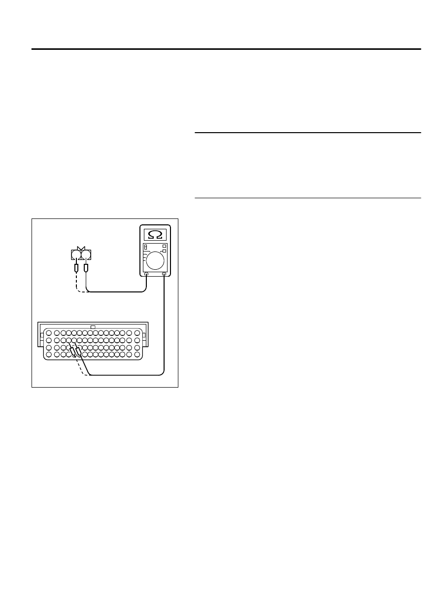
Disconnect  the  connector  B-20  and  B-10  measure  at  the
harness side.

(2)

Measure  the  resistance  between  connector  B-20  and
connector B-10.

  a

.

Knock sensor 1 connector B-20 (terminal No. 1) and ECM
connector B-10 (terminal No. 28).

b
.

Knock sensor 1 connector B-20 (terminal No. 2) and ECM
connector B-10 (terminal No. 29).

Should be less than 2 ohms.

Q:Is the measured resistance less than 2 ohms?

YES:

 Then go to Step 3.

NO:

 Repair it. Then go to Step 4.

MULTIPORT INJECTION SYSTEM (MFI) <DIAGNOSIS>

13Ab-431

DIAGNOSTIC TROUBLE CODE PROCEDURES

STEP 3. Replace the knock sensor 2.

ZC501967

AC404789

ZC5019680000

MB991824

MB991827

MB991910

Data link

connector

(1)

Replace the knock sensor 2.

To prevent damage to scan tool MB991958, always turn
the ignition switch to the "LOCK" (OFF) position before
connecting or disconnecting scan tool MB991958.

(2)

Connect scan tool MB991958 to the data link connector.

(3)

Turn the ignition switch to the "ON" position.

(4)

Erase the DTC.

(5)

Start the engine, and leave it idling for more than 2 seconds.
Then stop the engine.

(6)

After completing the test drive, read the DTC.

(7)

Turn the ignition switch to the "LOCK" (OFF) position.

Q:Is DTC P0333 set?

YES:

 Replace the ECM. When the ECM is replaced, register

the ID code. Refer to GROUP 42B, ID Code Registration
Judgment Table <Vehicles with KOS> P.42B-12or GROUP
42C, ID Code Registration Judgment Table <Vehicles with
WCM> P.42C-8.

NO:

 The inspection is complete.

STEP 4. Using scan tool MB991958, read the diagnostic
trouble code (DTC).

(1)

Turn the ignition switch to the "ON" position.

(2)

Start the engine, and leave it idling for more than 2 seconds.
Then stop the engine.

(3)

After completing the test drive, read the DTC.

(4)

Turn the ignition switch to the "LOCK" (OFF) position.

Q:Is DTC P0333 set?

YES:

 Retry the troubleshooting.

NO:

 The inspection is complete.

13Ab-432

MULTIPORT INJECTION SYSTEM (MFI) <DIAGNOSIS>

DIAGNOSTIC TROUBLE CODE PROCEDURES

DTC P0335: Crankshaft Position Sensor Circuit

M11310100225USA0000010000

ZK602850

1

2

3 4 5 6 7 8 9 10 11 12 13 14 15 16

17 18 19 20 21 22 23 24 25 26 27 28 29 30 31 32

33 34 35 36 37 38 39 40 41 42 43 44 45 46 47 48

49 50 51 52 53 54 55 56 57 58 59 60 61 62 63 64

3

2

1

CRANKSHAFT POSITION SENSOR CIRCUIT

CRANKSHAFT
POSITION SENSOR

B-119

(MU802348)

B-10

WHITE-BL

A

C

K

RED-BL

A

C

K

B

R

O

WN-WHIT

E

9

1

8

3

24

2

ENGINE
CONT RO L
MODULE

5 V

5 V

AA00

ZK603609AA00

Tie rod

Crankshaft
position sensor

B-119 (GR)

Connector: B-119

ZK603591

ECM

B-10 (GR)

Connector: B-10

AA00


MULTIPORT INJECTION SYSTEM (MFI) <DIAGNOSIS>

13Ab-433

DIAGNOSTIC TROUBLE CODE PROCEDURES

CIRCUIT OPERATION

The  crankshaft  position  sensor  power  is  supplied
from the ECM (terminal No. 9).

Terminal No. 1 of the crankshaft position sensor is
grounded with ECM (terminal No. 24).

A 5-volt voltage is applied on the crankshaft position
sensor  output  terminal  (terminal  No.  3)  from  the
ECM  (terminal  No.  8).  The  crankshaft  position
sensor  generates  a  pulse  signal  when  the  output
terminal is opened and grounded.

TECHNICAL DESCRIPTION

The  crankshaft  position  sensor  detects  the  crank
angle (position) of each cylinder, and converts that
data to pulse signals, then which are input to the
ECM.

When the engine is running, the crankshaft position
sensor outputs a pulse signal.

The ECM checks whether pulse signal is input while
the engine is cranking.

DESCRIPTIONS OF MONITOR METHODS

Crankshaft position sensor signal does not change.

Crankshaft  position  sensor  signal  is  not  normal
pattern.

MONITOR EXECUTION

Continuous

MONITOR EXECUTION CONDITIONS (Other
monitor and Sensor)

Other Monitor (There is no temporary DTC stored in
memory for the item monitored below)

Not applicable

Sensor (The sensor below is determined to be
normal)

Not applicable

13Ab-434

MULTIPORT INJECTION SYSTEM (MFI) <DIAGNOSIS>

DIAGNOSTIC TROUBLE CODE PROCEDURES


Content   ..  307  308  309  310   ..